sh030106u.pdf - 第37页
1. FUNCTI ONS AND CONF IGURATION 1 - 20 (2) 400 V clas s Servo am plifi er Rotary s ervo mot or Linear s ervo mot or (prima ry side) HG-SR HG-JR MR-J4- 60B4(-R J) 524 534 MR-J4- 100B4( -RJ) 1024 534 (Note ) 734 1034 MR-J…
1. FUNCTIONS AND CONFIGURATION
1 - 19
1.4 Combinations of servo amplifiers and servo motors
POINT
When a 1-phase 200 V AC input is used, the maximum torque of 400% cannot
be achieved with HG-JR series servo motor.
When you use the MR-J4-100B(-RJ) or MR-J4-200B(-RJ) with the 1-phase 200
V AC input, contact your local sales office for the torque characteristics of the
HG-UR series, HG-RR series, and HG-JR series servo motors.
(1) 200 V class
Servo amplifier
Rotary servo motor
Linear servo motor
(primary side)
Direct drive motor
HG-KR HG-MR HG-SR HG-UR HG-RR HG-JR
MR-J4-10B(-RJ) 053
13
053
13
MR-J4-20B(-RJ)
23 23
LM-U2PAB-05M-0SS0
LM-U2PBB-07M-1SS0
TM-RFM002C20
TM-RG2M002C30 (Note 1)
TM-RU2M002C30 (Note 1)
TM-RG2M004E30 (Note 1)
TM-RU2M004E30 (Note 1)
MR-J4-40B(-RJ)
43 43
LM-H3P2A-07P-BSS0
LM-H3P3A-12P-CSS0
LM-K2P1A-01M-2SS1
LM-U2PAD-10M-0SS0
LM-U2PAF-15M-0SS0
TM-RFM004C20
TM-RG2M004E30 (Note 1, 3)
TM-RU2M004E30 (Note 1, 3)
TM-RG2M009G30 (Note 1)
TM-RU2M009G30 (Note 1)
MR-J4-60B(-RJ)
51
52
53
LM-U2PBD-15M-1SS0 TM-RFM006C20
TM-RFM006E20
MR-J4-70B(-RJ)
73 73 72 73
LM-H3P3B-24P-CSS0
LM-H3P3C-36P-CSS0
LM-H3P7A-24P-ASS0
LM-K2P2A-02M-1SS1
LM-U2PBF-22M-1SS0
TM-RFM012E20
TM-RFM012G20
TM-RFM040J10
MR-J4-100B(-RJ)
81
102
53 (Note 2)
103
TM-RFM018E20
MR-J4-200B(-RJ)
121
201
152
202
152
103
153
73 (Note 2)
103 (Note 2)
153
203
LM-H3P3D-48P-CSS0
LM-H3P7B-48P-ASS0
LM-H3P7C-72P-ASS0
LM-FP2B-06M-1SS0
LM-K2P1C-03M-2SS1
LM-U2P2B-40M-2SS0
MR-J4-350B(-RJ)
301
352
202 203
153 (Note 2)
203 (Note 2)
353
LM-H3P7D-96P-ASS0
LM-K2P2C-07M-1SS1
LM-K2P3C-14M-1SS1
LM-U2P2C-60M-2SS0
TM-RFM048G20
TM-RFM072G20
TM-RFM120J10
MR-J4-500B(-RJ)
421
502
352
502
353
503
353 (Note 2)
503
LM-FP2D-12M-1SS0
LM-FP4B-12M-1SS0
LM-K2P2E-12M-1SS1
LM-K2P3E-24M-1SS1
LM-U2P2D-80M-2SS0
TM-RFM240J10
MR-J4-700B(-RJ)
702
503 (Note 2)
601
701M
703
LM-FP2F-18M-1SS0
LM-FP4D-24M-1SS0
MR-J4-11KB(-RJ)
801
12K1
11K1M
903
LM-FP4F-36M-1SS0
MR-J4-15KB(-RJ)
15K1
15K1M
LM-FP4F-48M-1SS0
MR-J4-22KB(-RJ)
20K1
25K1
22K1M
Note 1. This is available with servo amplifiers with software version C8 or later.
2. This combination increases the maximum torque of the servo motor to 400%.
3. This combination increases the rated torque and the maximum torque.

1. FUNCTIONS AND CONFIGURATION
1 - 20
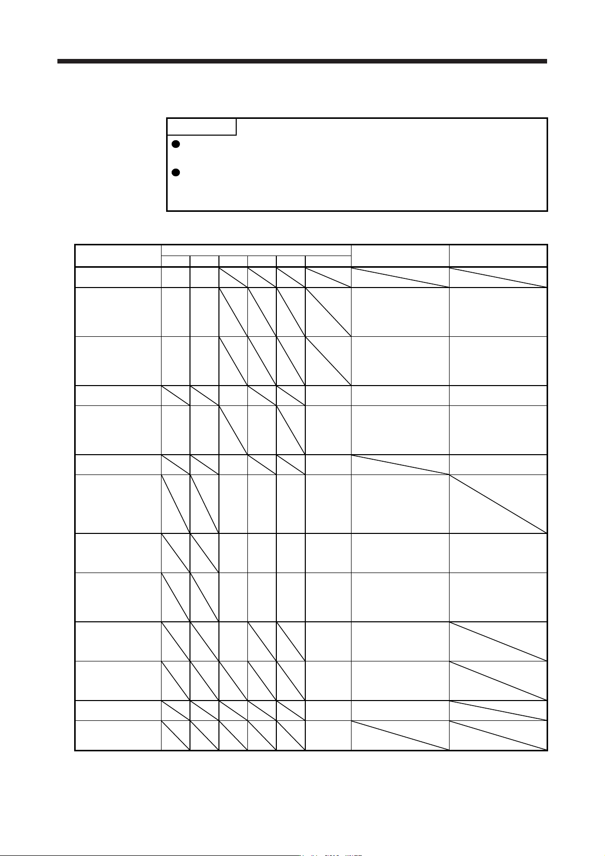
(2) 400 V class
Servo amplifier
Rotary servo motor
Linear servo motor
(primary side)
HG-SR HG-JR
MR-J4-60B4(-RJ) 524 534
MR-J4-100B4(-RJ)
1024
534 (Note)
734
1034
MR-J4-200B4(-RJ)
1524
2024
734 (Note)
1034 (Note)
1534
2034
MR-J4-350B4(-RJ)
3524
1534 (Note)
2034 (Note)
3534
MR-J4-500B4(-RJ)
5024
3534 (Note)
5034
MR-J4-700B4(-RJ)
7024
5034 (Note)
6014
701M4
7034
MR-J4-11KB4(-RJ)
8014
12K14
11K1M4
9034
MR-J4-15KB4(-RJ) 15K14
15K1M4
MR-J4-22KB4(-RJ) 20K14
25K14
22K1M4
LM-FP5H-60M-1SS0
Note. This combination is for increasin
g
the maximum torque of the servo motor to 400%.
(3) 100 V class
Servo amplifier
Rotary servo motor
Linear servo motor
(primary side)
Direct drive motor
HG-KR HG-MR
MR-J4-10B1(-RJ) 053
13
053
13
MR-J4-20B1(-RJ)
23 23
LM-U2PAB-05M-0SS0
LM-U2PBB-07M-1SS0
TM-RFM002C20
TM-RG2M002C30 (Note 1)
TM-RU2M002C30 (Note 1)
TM-RG2M004E30 (Note 1)
TM-RU2M004E30 (Note 1)
MR-J4-40B1(-RJ)
43 43
LM-H3P2A-07P-BSS0
LM-H3P3A-12P-CSS0
LM-K2P1A-01M-2SS1
LM-U2PAD-10M-0SS0
LM-U2PAF-15M-0SS0
TM-RFM004C20
TM-RG2M004E30 (Note 1, 2)
TM-RU2M004E30 (Note 1, 2)
TM-RG2M009G30 (Note 1)
TM-RU2M009G30 (Note 1)
Note 1. This is available with servo amplifiers with software version C8 or later.
2. This combination increases the rated torque and the maximum torque.

1. FUNCTIONS AND CONFIGURATION
1 - 21
1.5 Function list
The following table lists the functions of this servo. For details of the functions, refer to each section of the
detailed description field.
Function Description
Detailed
explanation
Model adaptive control
This realizes a high response and stable control following the ideal model. The two-
degrees-of-freedom-model model adaptive control enables you to set a response to
the command and response to the disturbance separately. Additionally, this function
can be disabled. Refer to section 7.5 for disabling this function. This is used with
servo amplifiers with software version B4 or later.
Position control mode This servo amplifier is used as a position control servo.
Speed control mode This servo amplifier is used as a speed control servo.
Torque control mode This servo amplifier is used as a torque control servo.
High-resolution encoder
High-resolution encoder of 4194304 pulses/rev is used as the encoder of the rotary
servo motor compatible with the MELSERVO-J4 series.
Absolute position detection
system
Merely setting a home position once makes home position return unnecessary at
every power-on.
Chapter 12
Gain switching function
You can switch gains during rotation and during stop, and can use an input device to
switch gains during operation.
Section 7.2
Advanced vibration
suppression control II
This function suppresses vibration at the arm end or residual vibration. Section 7.1.5
Machine resonance
suppression filter
This is a filter function (notch filter) which decreases the gain of the specific frequency
to suppress the resonance of the mechanical system.
Section 7.1.1
Shaft resonance suppression
filter
When a load is mounted to the servo motor shaft, resonance by shaft torsion during
driving may generate a mechanical vibration at high frequency. The shaft resonance
suppression filter suppresses the vibration.
Section 7.1.3
Adaptive filter II
Servo amplifier detects mechanical resonance and sets filter characteristics
automatically to suppress mechanical vibration.
Section 7.1.2
Low-pass filter
Suppresses high-frequency resonance which occurs as servo system response is
increased.
Section 7.1.4
Machine analyzer function
Analyzes the frequency characteristic of the mechanical system by simply connecting
a MR Configurator2 installed personal computer and servo amplifier.
MR Configurator2 is necessary for this function.
Robust filter
This function provides better disturbance response in case low response level that
load to motor inertia ratio is high for such as roll send axes.
[Pr. PE41]
Slight vibration suppression
control
Suppresses vibration of ±1 pulse produced at a servo motor stop. [Pr. PB24]
Auto tuning
Automatically adjusts the gain to optimum value if load applied to the servo motor
shaft varies.
Section 6.3
Brake unit
Used when the regenerative option cannot provide enough regenerative power.
Can be used for the 5 kW or more servo amplifier.
Section 11.3
Power regeneration converter
Used when the regenerative option cannot provide enough regenerative power.
Can be used for the 5 kW or more servo amplifier.
Section 11.4
Multifunction regeneration
converter
Use this function if the regenerative option does not have sufficient regenerative
capacity.
Section 11.19
Regenerative option
Used when the built-in regenerative resistor of the servo amplifier does not have
sufficient regenerative capability for the regenerative power generated.
Section 11.2
Alarm history clear Alarm history is cleared. [Pr. PC21]
Output signal selection
(device settings)
The output devices including ALM (Malfunction) and DB (Dynamic brake interlock)
can be assigned to certain pins of the CN3 connector.
[Pr. PD07] to
[Pr. PD09]
Output signal (DO) forced
output
Output signal can be forced on/off independently of the servo status.
Use this function for checking output signal wiring, etc.
Section 4.5.1
(1) (d)
Test operation mode
Jog operation, positioning operation, motor-less operation, DO forced output, and
program operation can be used.
MR Configurator2 is necessary for this function.
Section 4.5
Analog monitor output Servo status is output in terms of voltage in real time.
[Pr. PC09],
[Pr. PC10]
MR Configurator2
Using a personal computer, you can perform the parameter setting, test operation,
monitoring, and others.
Section 11.7
Linear servo system Linear servo system can be configured using a linear servo motor and linear encoder. Chapter 14