sh030106u.pdf - 第349页
11. OPT ION S AND P ERI PHER AL EQU IPMENT 11 - 28 Brake unit Resi stor unit Number of connected units Permi ssibl e continuous power [k W] Resultant resistanc e [Ω] Applic able servo amplifi er (Note 3) 400 V class FR-B…
11. OPTIONS AND PERIPHERAL EQUIPMENT
11 - 27
11.3 FR-BU2-(H) brake unit
POINT
Use a 200 V class brake unit and a resistor unit with a 200 V class servo
amplifier, and a 400 V class brake unit and a resistor unit with a 400 V class
servo amplifier. Combination of different voltage class units cannot be used.
When a brake unit and a resistor unit are installed horizontally or diagonally, the
heat dissipation effect diminishes. Install them on a flat surface vertically.
The temperature of the resistor unit case will be higher than the ambient
temperature by 100 ˚C or over. Keep cables and flammable materials away from
the case.
Ambient temperature condition of the brake unit is between -10 ˚C and 50 ˚C.
Note that the condition is different from the ambient temperature condition of the
servo amplifier (between 0 ˚C and 55 ˚C).
Configure the circuit to shut down the power-supply with the alarm output of the
brake unit and the resistor unit under abnormal condition.
Use the brake unit with a combination indicated in section 11.3.1.
To perform continuous regenerative operation, use the FR-RC-(H) power
regeneration converter, FR-CV-(H) power regeneration common converter, or
FR-XC-(H) multifunction regeneration converter.
Brake unit and regenerative options (Regenerative resistor) cannot be used
simultaneously.
Connect the brake unit to the bus of the servo amplifier. As compared to the MR-RB regenerative option, the
brake unit can return larger power. Use the brake unit when the regenerative option cannot provide sufficient
regenerative capability.
When using the brake unit, set [Pr. PA02] to "_ _ 0 1".
When using the brake unit, always refer to the FR-BU2 Instruction Manual.
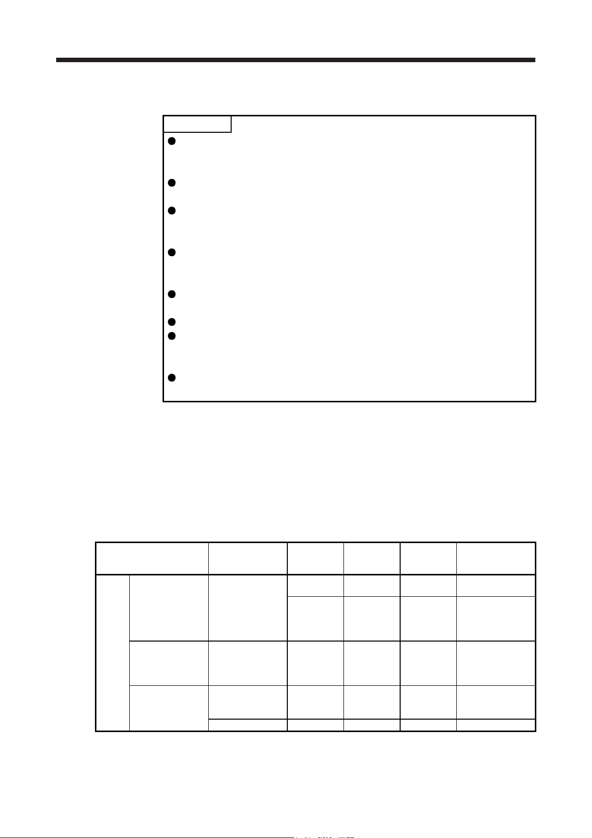
11.3.1 Selection
Use a combination of servo amplifier, brake unit and resistor unit listed below.
Brake unit Resistor unit
Number of
connected
units
Permissible
continuous
power [kW]
Resultant
resistance [Ω]
Applicable servo
amplifier (Note 3)
200 V
class
FR-BU2-15K FR-BR-15K 1 0.99 8
MR-J4-500B(-RJ)
(Note 1)
2 (parallel) 1.98 4 MR-J4-500B(-RJ)
MR-J4-700B(-RJ)
MR-J4-11KB(-RJ)
MR-J4-15KB(-RJ)
FR-BU2-30K FR-BR-30K 1 1.99 4 MR-J4-500B(-RJ)
MR-J4-700B(-RJ)
MR-J4-11KB(-RJ)
MR-J4-15KB(-RJ)
FR-BU2-55K FR-BR-55K 1 3.91 2 MR-J4-11KB(-RJ)
MR-J4-15KB(-RJ)
MR-J4-22KB(-RJ)
MT-BR5-55K 1 5.5 2 MR-J4-22KB(-RJ)
11. OPTIONS AND PERIPHERAL EQUIPMENT
11 - 28
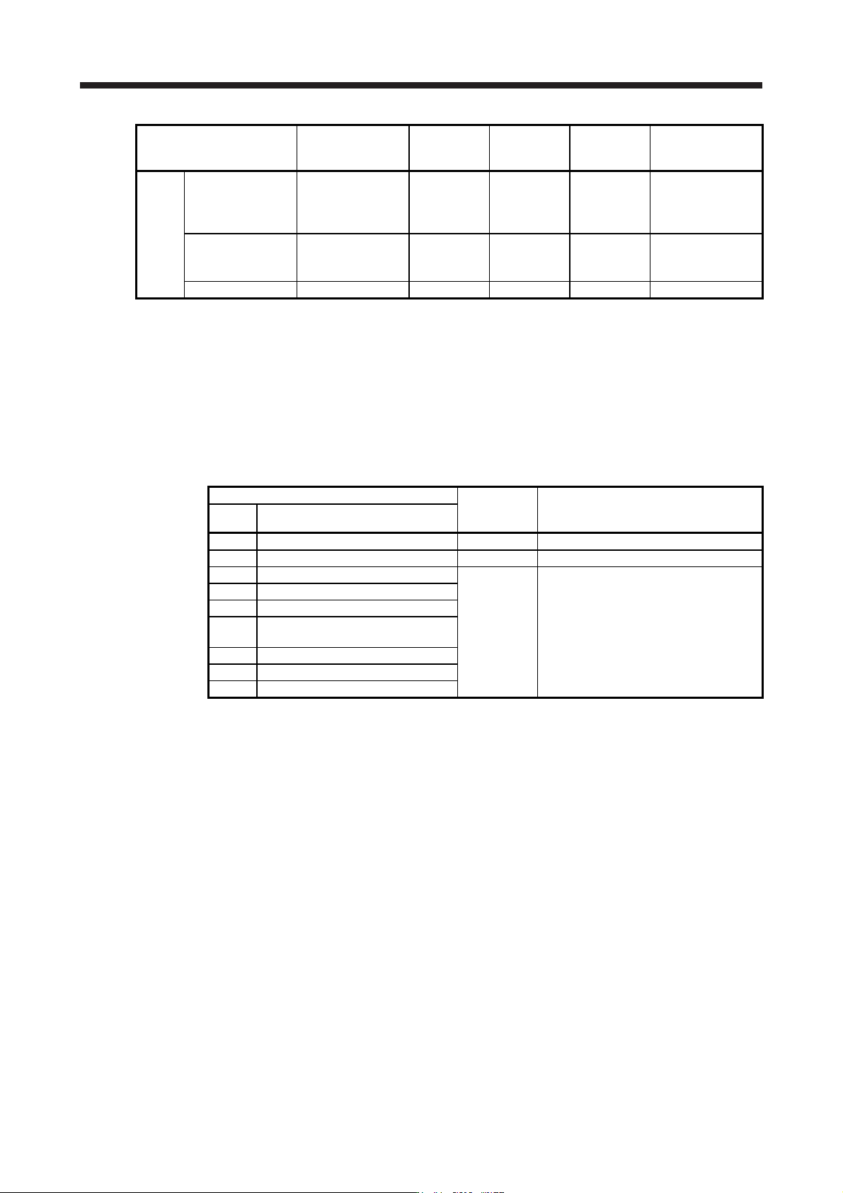
Brake unit Resistor unit
Number of
connected
units
Permissible
continuous
power [kW]
Resultant
resistance [Ω]
Applicable servo
amplifier (Note 3)
400 V
class
FR-BU2-H30K FR-BR-H30K 1 1.99 16 MR-J4-500B4(-RJ)
MR-J4-700B4(-RJ)
MR-J4-11KB4(-RJ)
(Note 2)
FR-BU2-H55K FR-BR-H55K 1 3.91 8 MR-J4-11KB4(-RJ)
MR-J4-15KB4(-RJ)
MR-J4-22KB4(-RJ)
FR-BU2-H75K MT-BR5-H75K 1 7.5 6.5 MR-J4-22KB4(-RJ)
Note 1. Onl
y
when usin
g
servo motor HG-RR353/HG-UR352
2. When HG-JR11K1M4 servo motor is used, limit the torque during power running to 180% or less, or the servo
motor speed to 1800 r/min or less.
3. When the brake unit is selected by using the capacity selection software, a brake unit other than the combinations
listed may be shown. Refer to the combinations displayed on the capacity selection software for detailed
combinations.
11.3.2 Brake unit parameter setting
Whether a parameter can be changed or not is listed below.
Parameter
Change
possible/
impossible
Remark
No. Name
0 Brake mode switchover Impossible Do not change the parameter.
1 Monitor display data selection Possible Refer to the FR-BU2 Instruction Manual.
2 Input terminal function selection 1 Impossible Do not change the parameter.
3 Input terminal function selection 2
77 Parameter write selection
78
Cumulative energization time
carrying-over times
CLr Parameter clear
ECL Alarm history clear
C1 For manufacturer setting
11. OPTIONS AND PERIPHERAL EQUIPMENT
11 - 29
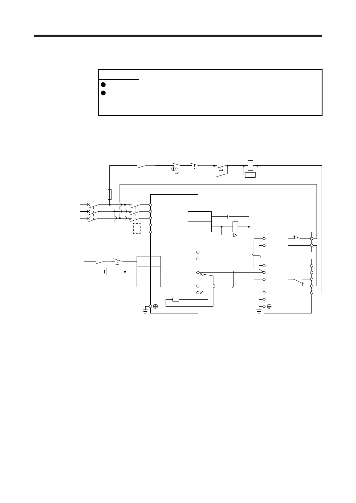
11.3.3 Connection example
POINT
EM2 has the same function as EM1 in the torque control mode.
Connecting PR terminal of the brake unit to the P+ terminal of the servo amplifier
results in brake unit malfunction. Always connect the PR terminal of the brake
unit to the PR terminal of the resistor unit.
(1) Combination with FR-BR-(H) resistor unit
(a) When connecting a brake unit to a servo amplifier
1) 200 V class
Emergency stop switch
3
DOCOM
ALM
Servo amplifier
15
CN3
(Note 9)
MC
MCCB
(Note 1)
Power
supply
L1
L2
L3
L11
L21
ALM
RA1
OFF
MC
ON
MC
SK
P3
P4
(Note 3)
P+
N-
C
(Note 2)
(Note 7)
(Note 11)
N/-
P/+
BUE
SD
PR
B
C
A
SD
MSG
(Note 4)
(Note 6)
FR-BU2
FR-BR
P
PR
TH2
TH1
(Note 5)
(Note 8)
RA1
CN3
(Note 10)
Main circuit
power supply
24 V DC (Note 12)
5
10
EM2
DICOM
DICOM
20
24 V DC (Note 12)
Note 1. For the power supply specifications, refer to section 1.3.
2. When using the servo amplifier of 7 kW or less, make sure to disconnect the wiring of built-in regenerative resistor (5 kW or
less: P+ and D, 7 kW: P+ and C). For the servo amplifier of 11 kW to 22 kW, do not connect a supplied regenerative resistor to
the P+ and C terminals.
3. Between P3 and P4 is connected by default. When using the power factor improving DC reactor, remove the short bar
between P3 and P4. Refer to section 11.11 for details. Additionally, a power factor improving DC reactor and power factor
improving AC reactor cannot be used simultaneously.
4. Connect P/+ and N/- terminals of the brake unit to a correct destination. Incorrect connection destination results in servo
amplifier and brake unit malfunction.
5. Contact rating: 1b contact, 110 V AC, 5 A/220 V AC, 3 A
Normal condition: TH1-TH2 is conductin
g
. Abnormal condition: TH1-TH2 is not conductin
g
.
6. Contact rating: 230 V AC, 0.3 A/30 V DC, 0.3 A
Normal condition: B-C is conducting./A-C is not conducting. Abnormal condition: B-C is not conducting./A-C is conducting.
7. Do not connect more than one cable to each P+ and N- terminals of the servo amplifier.
8.
A
lwa
y
s connect BUE and SD terminals.
(
factor
y
-wired
)
9. Depending on the main circuit voltage and operation pattern, bus voltage decreases, and that may cause the forced stop
deceleration to shift to the dynamic brake deceleration. When dynamic brake deceleration is not required, slow the time to turn
off the ma
g
netic contactor.
10. Configure a circuit to turn off EM2 when the main circuit power is turned off to prevent an unexpected restart of the servo
amplifier.
11. When wires used for L11 and L21 are thinner than wires used for L1, L2, and L3, use a molded-case circuit breaker.
12. The illustration of the 24 V DC power supply is divided between input signal and output signal for convenience. However, they
can be confi
g
ured b
y
one.