sh030106u.pdf - 第617页
17. APPLICATIO N OF FUNCTIONS 17 - 66 4) Lost mo tion com pensa tion t iming ([ Pr. PX4 1]) You can s et the delay time of the l ost motio n com pensatio n star t tim ing wit h this p arameter. When a protrus ion occurs …
17. APPLICATION OF FUNCTIONS
17 - 65
(9) Lost motion compensation function
POINT
The lost motion compensation function is enabled only in the position control
mode.
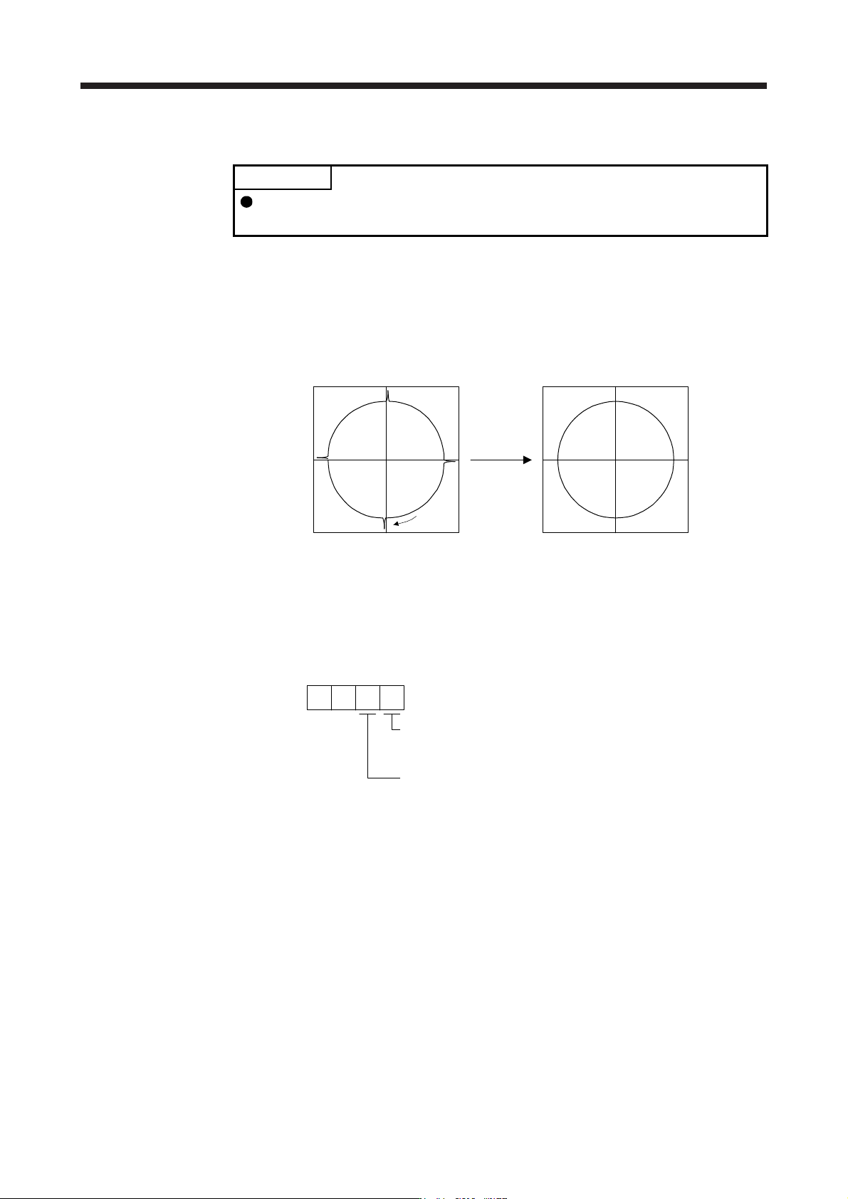
The lost motion compensation function corrects response delays (caused by a non-sensitive band due to
friction, twist, expansion, and backlash) caused when the machine travel direction is reversed. This
function contributes to improvement for protrusions that occur at a quadrant change and streaks that
occur at a quadrant change during circular cutting.
This function is effective when a high follow-up performance is required such as drawing an arc with an
X-Y table.
The locus before compensation The locus after compensation
Compensation
Travel
direction
(a) Parameter setting
Setting [Pr. PX36] to [Pr. PX42] enables the lost motion compensation function.
1) Lost motion compensation function selection ([Pr. PX40])
Select the lost motion compensation function.
Lost motion compensation selection
0: Lost motion compensation disabled
1: Lost motion compensation enabled
0
Unit setting of lost motion compensation non-sensitive band
0: 1 pulse unit
1: 1 kpulse unit
[Pr. PX40]
0
2) Lost motion compensation ([Pr. PX36]/[Pr. PX37])
Set the same value for the lost motion compensation for each of when the forward rotation
switches to the reverse rotation and when the reverse rotation switches to the forward rotation.
When the heights of protrusions differ depending on the travel direction, set the different
compensation for each travel direction. Set a value twice the usual friction torque and adjust the
value while checking protrusions.
3) Torque offset ([Pr. PX39])
For a vertical axis, unbalanced torque occurs due to the gravity. Although setting the torque offset
is usually unnecessary, setting unbalanced torque of a machine as a torque offset cancels the
unbalanced torque. The torque offset does not need to be set for a machine not generating
unbalanced torque. The torque offset cannot be used for linear servo motors and direct drive
motors. Set 0.00%.

17. APPLICATION OF FUNCTIONS
17 - 66
4) Lost motion compensation timing ([Pr. PX41])
You can set the delay time of the lost motion compensation start timing with this parameter.
When a protrusion occurs belatedly, set the lost motion compensation timing corresponding to the
protrusion occurrence timing.
5) Lost motion compensation non-sensitive band ([Pr. PX42])
When the travel direction reverses frequently around the zero speed, unnecessary lost motion
compensation is triggered by the travel direction switching. By setting the lost motion
compensation non-sensitive band, the speed is recognized as 0 when the fluctuation of the droop
pulse is the setting value or less.
When the value of this parameter is changed, the compensation timing is changed. Adjust the
value of Lost motion compensation timing ([Pr. PX41]).
6) Lost motion filter setting ([Pr. PX38])
Changing the value of this parameter is usually unnecessary. When a value other than 0.0 ms is
set in this parameter, the high-pass filter output value of the set time constant is applied to the
compensation and lost motion compensation continues.
(b) Adjustment procedure of the lost motion compensation function
1) Measuring the load current
Measure the load currents during the forward direction feed and reverse direction feed with MR
Configurator2.
2) Setting the lost motion compensation
Calculate the friction torque from the measurement result of (9) (b) 1) in this section and set a
value twice the friction torque in [Pr. PX36] and [Pr. PX37] as lost motion compensation.
Friction torque [%] =
2
|(load current during feed in the forward rotation direction [%]) -
(load current during feed in the reverse rotation direction [%])|
3) Checking protrusions
Drive the servo motor and check that the protrusions are corrected.
4) Adjusting the lost motion compensation
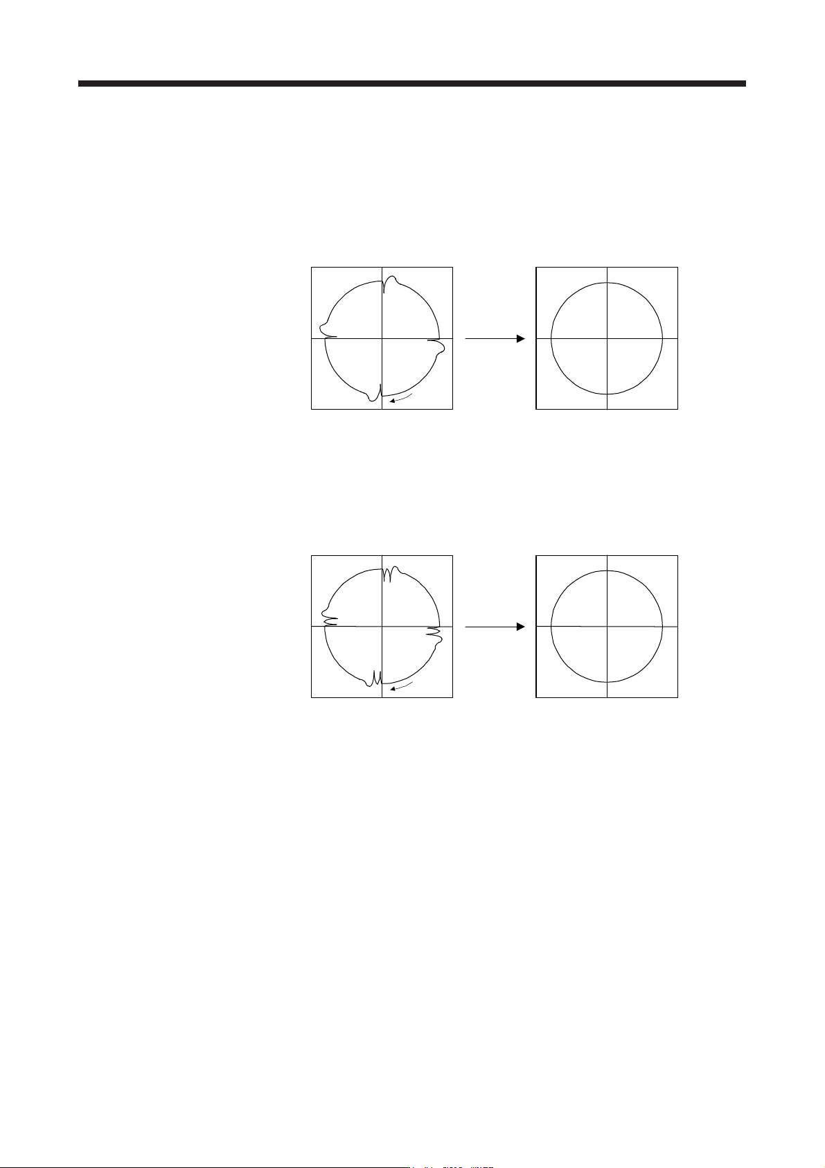
When protrusions still occur, the compensation is insufficient. Increase the lost motion
compensation by approximately 0.5% until the protrusions are eliminated. When notches occur,
the compensation is excessive. Decrease the lost motion compensation by approximately 0.5%
until the notches are eliminated. Different values can be set as the compensation for each of
when the forward rotation (CCW) switches to the reverse rotation (CW) and when the reverse
rotation (CW) switches to the forward rotation (CCW).
The locus before compensation The locus after compensation
Compensation
Travel
direction
17. APPLICATION OF FUNCTIONS
17 - 67
5) Adjusting the lost motion compensation timing
When the machine has low rigidity, the speed loop gain is set lower than the standard setting
value, or the servo motor is rotating at high speed, quadrant projections may occur behind the
quadrant change points. In this case, you can suppress the quadrant projections by delaying the
lost motion compensation timing with [Pr. PX41 Lost motion compensation timing]. Increase the
setting value of [Pr. PX41] from 0 ms (Initial value) by approximately 0.5 ms to adjust the
compensation timing.
Before timing delay compensation After timing delay compensation
Compensation
Travel
direction
6) Adjusting the lost motion compensation non-sensitive band
When the lost motion is compensated twice around a quadrant change point, set [Pr. PX42 Lost
motion compensation non-sensitive band]. Increase the setting value so that the lost motion is not
compensated twice. Setting [Pr. PX42] may change the compensation timing. Adjust the lost
motion compensation timing of (9) (b) 5) in this section.
Before timing delay compensation After timing delay compensation
Compensation
Travel
direction