sh030106u.pdf - 第505页
15. USIN G A DI REC T DRIV E MOTOR 15 - 2 15. 1.2 Servo system with auxilia ry equi pment CAUTION Connectin g a direc t driv e motor for differ ent axis to the U, V, W, or CN2 may cause a m alfuncti on. POINT Equipment o…
15. USING A DIRECT DRIVE MOTOR
15 - 1
15. USING A DIRECT DRIVE MOTOR
CAUTION
When using the direct drive motor, read the "Direct Drive Motor Instruction
Manual".
POINT
Refer to section 1.4 for the software version of a servo amplifier that is
compatible with the direct drive servo system.
15.1 Functions and configuration
15.1.1 Summary
The fields of semiconductor/LCD manufacturing systems, mounters, and others have strong demands for
high accuracy and efficiency. Therefore, the number of systems using a direct drive motor for a drive axis
has been increasing. The direct drive servo system includes the following features.
(1) Performance
(a) The direct drive servo system ensures the high-rigidity and the high-torque. A high-resolution
encoder enables the high-accuracy control.
(b) The high-resolution encoder contributes to the high-indexer accuracy.
(c) Since reducer is no longer required, no backlash occurs. In addition, the settling time is reduced, and
the high-frequency operation is enabled.
(d) Since reducer is no longer required, the motor does not deteriorate with time by reducer.
(2) Mechanism
(a) The motor's low profile design contributes to compact moving part of the machine and a low center
of gravity for enhanced equipment stability.
(b) The motor has an inner rotor with hollow shaft which enables cables and pipes to be passed through.
(c) Lubrication and the maintenance due to abrasion are not required.
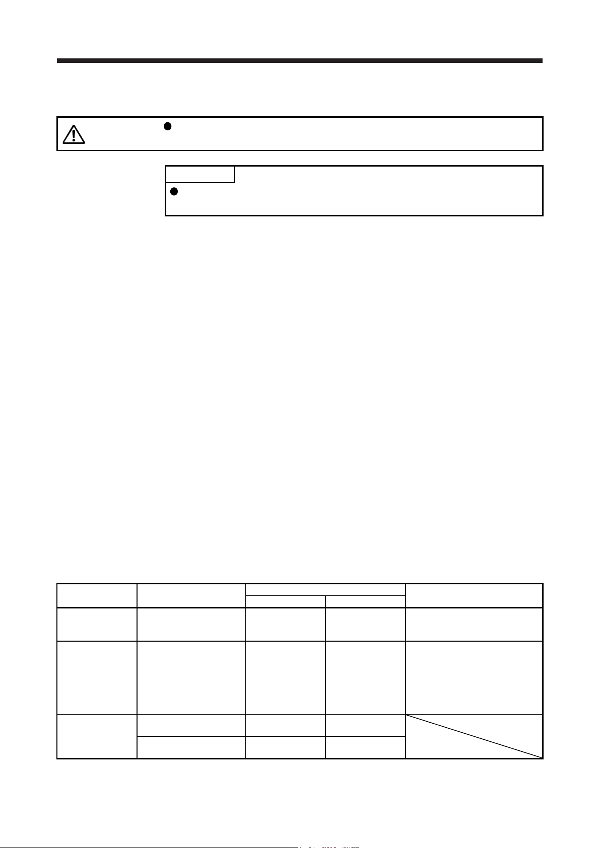
The following shows the differences between the direct drive motor and the rotary servo motor.
Category Item
Differences
Remark
Direct drive motor Rotary servo motor
External I/O signal
FLS (Upper stroke limit),
RLS (Lower stroke limit)
Required
(for magnetic pole
detection)
Not required
Automatically turns on in the
parameter setting.
Motor pole
adjustment
Magnetic pole detection Required Not required
(default setting)
Automatically executed at the first
servo-on after the power is turned
on.
For the absolute position detection
system, [Pr. PL01] can disable the
magnetic pole detection. (Refer to
(3) (a) of section 15.3.2.)
Absolute position
detection system
Absolute position encoder
battery
Required Required
Absolute position storage
unit (MR-BTAS01)
Required Not required
15. USING A DIRECT DRIVE MOTOR
15 - 2
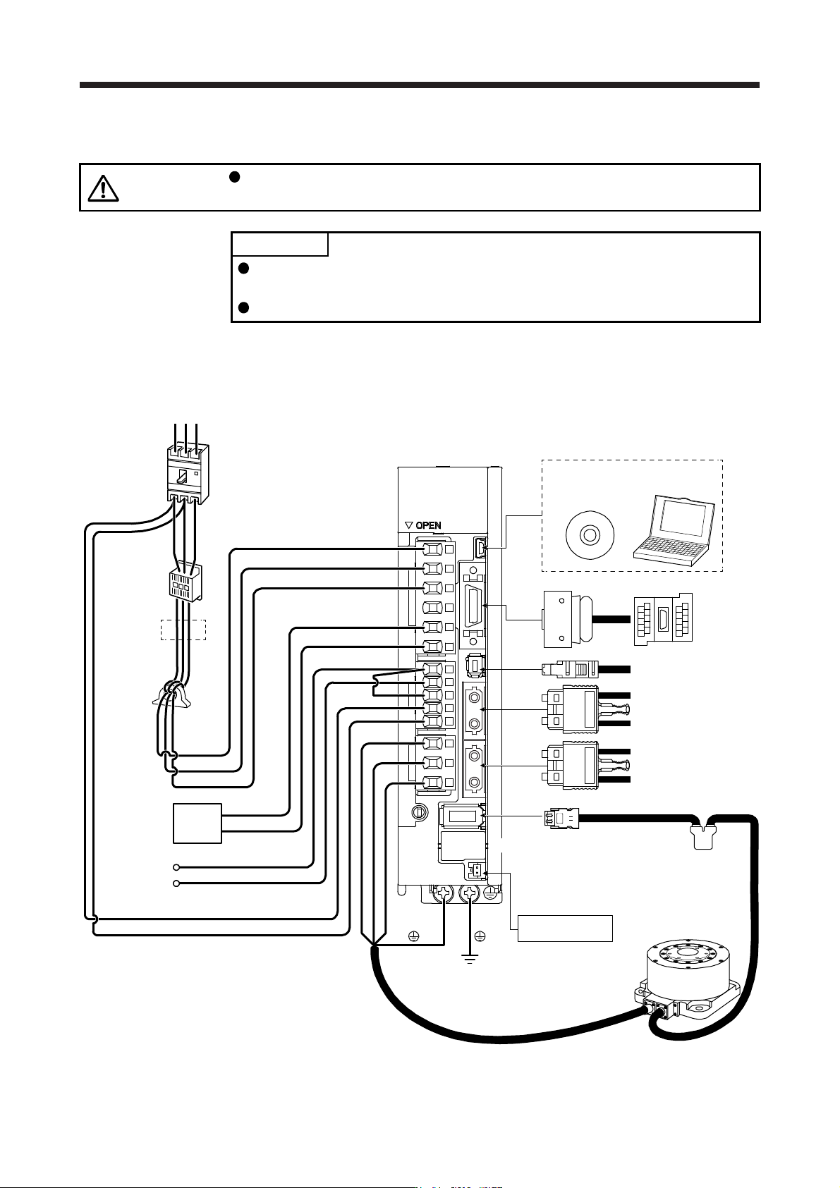
15.1.2 Servo system with auxiliary equipment
CAUTION
Connecting a direct drive motor for different axis to the U, V, W, or CN2 may
cause a malfunction.
POINT
Equipment other than the servo amplifier and direct drive motor are optional or
recommended products.
When using the direct drive motor, set [Pr. PA01] to "_ _ 6 _".
The configuration diagram is an example of MR-J4-20B. When using the other servo amplifiers, the
configuration will be the same as rotary servo motors except for connections of direct drive motors. Refer to
section 1.8 depending on servo amplifiers you use.
(Note 4)
Battery unit
CN4
(Note 6)
Absolute position
storage unit
MR-BTAS01
Direct drive motor
Line noise
filter
(FR-BSF01)
CN5
Regenerative
option
P+
C
L11
L21
P3
P4
Personal
computer
MR Configurator2
CN3
CN8
CN1A
CN1B
CN2
W
V
U
L1
L2
L3
(Note 1)
Power factor
improving DC
reactor
(FR-HEL)
Junction
terminal
block
To safety relay or
MR-J3-D05 safety
logic unit
Servo system controller
or previous servo
amplifier CN1B
Next servo amplifier
CN1A or cap
(Note 2)
Power supply
RS T
D
(Note 5)
Molded-case
circuit breaker
(MCCB)
(Note 3)
Magnetic
contactor
(MC)
(Note 7)
15. USING A DIRECT DRIVE MOTOR
15 - 3
Note 1. The power factor improving AC reactor can also be used. In this case, the power factor improving DC reactor cannot be used.
When not usin
g
the power factor improvin
g
DC reactor, short P3 and P4.
2.
A
1-phase 200 V AC to 240 V AC power supply may be used with the servo amplifier of MR-J4-200B(-RJ) or less. For 1-phase
200 V AC to 240 V AC, connect the power supply to L1 and L3. Leave L2 open. For the power supply specifications, refer to
section 1.3.
3. Depending on the main circuit voltage and operation pattern, bus voltage decreases, and that may cause the forced stop
deceleration to shift to the dynamic brake deceleration. When dynamic brake deceleration is not required, slow the time to turn
off the ma
g
netic contactor.
4. The batter
y
unit is used for the absolute position detection s
y
stem.
(
Refer to chapter 12.
)
5.
A
lwa
y
s connect P+ and D. When usin
g
the re
g
enerative option, refer to section 11.2.
6. The absolute position stora
g
e unit is used for the absolute position detection s
y
stem.
7. This is for MR-J4-
_
B_. MR-J4-
_
B
_
-RJ has a CN2L connector. However, CN2L is not used for the direct drive servo s
y
stem.
15.2 Signals and wiring
WARNING
Any person who is involved in wiring should be fully competent to do the work.
Before wiring, turn off the power and wait for 15 minutes or more until the charge
lamp turns off. Then, confirm that the voltage between P+ and N- is safe with a
voltage tester and others. Otherwise, an electric shock may occur. In addition,
when confirming whether the charge lamp is off or not, always confirm it from the
front of the servo amplifier.
Ground the servo amplifier and the direct drive motor securely.
Do not attempt to wire the servo amplifier and the direct drive motor until they
have been installed. Otherwise, it may cause an electric shock.
The cables should not be damaged, stressed, loaded, or pinched. Otherwise, it
may cause an electric shock.
To avoid an electric shock, insulate the connections of the power supply terminals.
CAUTION
Wire the equipment correctly and securely. Otherwise, the direct drive motor may
operate unexpectedly, resulting in injury.
Connect cables to the correct terminals. Otherwise, a burst, damage, etc. may
occur.
Ensure that polarity (+/-) is correct. Otherwise, a burst, damage, etc. may occur.
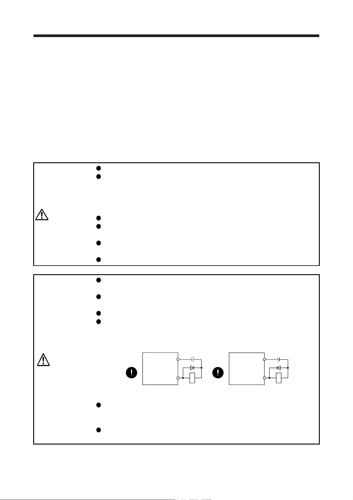
The surge absorbing diode installed to the DC relay for control output should be
fitted in the specified direction. Otherwise, the emergency stop and other
protective circuits may not operate.
DOCOM
24 V DC
Servo amplifier
RA
For sink output interface
Control output
signal
DOCOM
Control output
signal
24 V DC
Servo amplifier
RA
For source output interface
Use a noise filter, etc. to minimize the influence of electromagnetic interference.
Electromagnetic interference may be given to the electronic equipment used near
the servo amplifier.
Do not install a power capacitor, surge killer, or radio noise filter (FR-BIF option)
with the power wire of the direct drive motor.