sh030106u.pdf - 第558页
17. APPLICATIO N OF FUNCTIONS 17 - 7 (3) Setting of MR Conf igurat or2 To use in the J3 com patibilit y mode, ma ke the syst em setti ng as fol lows. Operation m ode in J3 c ompatibility m ode S ystem setti ng MR-J3-B st…
17. APPLICATION OF FUNCTIONS
17 - 6
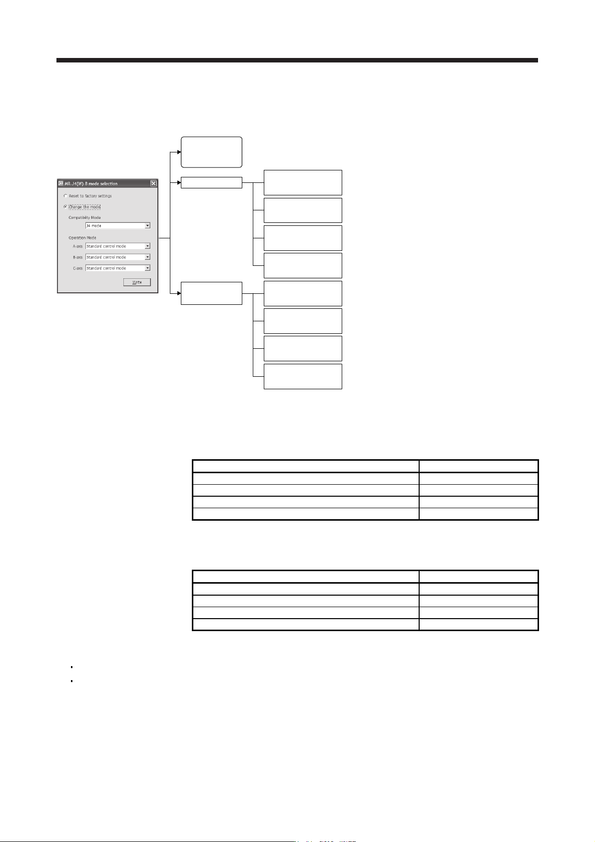
(2) Mode selection using the application "MR-J4(W)-B mode selection" or "MR Mode Change"
You can set the factory setting, J4 mode/J3 compatibility mode, and operation mode with the dedicated
application.
"MR-J4(W)-B mode selection"
or "MR Mode Change"
J4 mode
J3 compatibility
mode
J4 mode/J3
compatibility mode
automatic
identification
Standard control
(rotary servo motor)
Direct drive motor
control
Linear servo motor
control
Fully closed loop
control
Standard control
(rotary servo motor)
Direct drive motor
control
Linear servo motor
control
Fully closed loop
control
Factory setting
Fixed to the J4 mode (Standard control (rotary servo
motor))
Fixed to the J4 mode (Fully closed loop control)
Fixed to the J4 mode (Linear servo motor control)
Fixed to the J4 mode (Direct drive motor control)
Fixed to the J3 compatibility mode (Standard control
(rotary servo motor)) [Equivalent to MR-J3-B]
Fixed to the J3 compatibility mode (Fully closed loop
control) [Equivalent to MR-J3-B-RJ006]
Fixed to the J3 compatibility mode (Linear servo motor
control) [Equivalent to MR-J3-B-RJ004]
Fixed to the J3 compatibility mode (Direct drive motor
control) [Equivalent to MR-J3-B-RJ080W]
17.1.5 How to use the J3 compatibility mode
(1) Setting of the controller
To use in the J3 compatibility mode, select MR-J3 series in the system setting window.
Operation mode in J3 compatibility mode System setting
MR-J3-B standard control mode (rotary servo motor) Select MR-J3-_B.
MR-J3-B fully closed loop control mode Select MR-J3-_B fully closed.
MR-J3-B linear servo motor control mode Select MR-J3-_B linear.
MR-J3-B DD motor control mode Select MR-J3-_B DD motor.
(2) Setting of MR Configurator
To use in the J3 compatibility mode, make the system setting as follows.
Operation mode in J3 compatibility mode System setting
MR-J3-B standard control mode (rotary servo motor) Select MR-J3-_B.
MR-J3-B fully closed loop control mode Select MR-J3-_B fully closed.
MR-J3-B linear servo motor control mode Select MR-J3-_B linear.
MR-J3-B DD motor control mode Select MR-J3-_B DD motor.
Cautions for using MR Configurator
The gain search cannot be used. You can use the advanced gain search.
The C-axis of MR-J4W3-_B cannot be set with MR Configurator. Use MR Configurator2 for it.

17. APPLICATION OF FUNCTIONS
17 - 7
(3) Setting of MR Configurator2
To use in the J3 compatibility mode, make the system setting as follows.
Operation mode in J3 compatibility mode System setting
MR-J3-B standard control mode (rotary servo motor) Select MR-J3-_B.
MR-J3-B fully closed loop control mode Select MR-J3-_B fully closed.
MR-J3-B linear servo motor control mode Select MR-J3-_B linear.
MR-J3-B DD motor control mode Select MR-J3-_B DD motor.
Cautions for using MR Configurator2
Use MR Configurator2 with software version 1.12N or later. Older version than 1.12N cannot be used.
Information about existing models (MR-J3) cannot be updated with the parameter setting range update
function. Register a new model to use.
The alarm will be displayed by 3 digits.
The robust disturbance compensation cannot be used.
17.1.6 Cautions for switching J4 mode/J3 compatibility mode
The J3 compatibility mode of the operation mode is automatically identified by factory setting depending on a
connected encoder. If a proper encoder is not connected at the first connection, the system will not start
normally due to a mismatch with a set mode with the controller. (For the J4 mode, you can set the operation
mode with [Pr. PA01].) For example, if the controller is connected without connecting a linear encoder at
linear servo motor driving, the servo amplifier will be the standard control mode (rotary servo motor). The
system will not start because the controller is connected with the linear servo motor driving amplifier.
When the operation mode mismatches, the servo amplifier will display [AL. 3E.1 Operation mode error].
Restore the factory settings or configure the correct settings (J4 mode/J3 compatibility mode and operation
mode) using the application "MR-J4(W)-B mode selection" or "MR Mode Change" described in section
17.1.1.

17. APPLICATION OF FUNCTIONS
17 - 8
17.1.7 Cautions for the J3 compatibility mode
The J3 compatibility mode are partly changed and has restrictions compared with MR-J3 series.
(1) The alarm display was changed from 2 digits (_ _) to 3 digits (_ _. _). The alarm detail number (._) is
displayed in addition to the alarm No (_ _). The alarm No. (_ _) is not changed.
(2) When the power of the servo amplifier is cut or fiber-optic cable is disconnected, the same type
communication can be cut regardless of connection order. When you power on/off the servo amplifier
during operation, use the connect/disconnect function of the controller. Refer to the following manuals for
detail.
MELSEC iQ-R Motion Controller Programming Manual (Common) (R16MTCPU/R32MTCPU) (IB-
0300237) "5.3.1 Connect/disconnect function of SSCNET communication"
Motion controller Q series Programming Manual (COMMON) (Q173D(S)CPU/Q172D(S)CPU) (IB-
0300134) "4.11.1 Connect/disconnect function of SSCNET communication"
MELSEC iQ-R Simple Motion Module User's Manual (Application)
(RD77MS2/RD77MS4/RD77MS8/RD77MS16) (IB-0300247) "8.12 Connect/Disconnect Function of
SSCNET Communication"
MELSEC-Q QD77MS Simple Motion Module User's Manual (IB-0300185) "14.12 Connect/disconnect
function of SSCNET communication"
MELSEC-L LD77MH Simple Motion Module User's Manual (IB-0300172) "14.13 Connect/disconnect
function of SSCNET communication"
MELSEC-L LD77MS Simple Motion Module User's Manual (Positioning Control) (IB-0300211) "14.13
Connect/disconnect function of SSCNET communication"
(3) The J3 compatibility mode has a functional compatibility. However, the operation timing may differ.
Check the operation timing on customer side to use.
(4) The J3 compatibility mode is not compatible with high-response control set by [Pr. PA01 Operation
mode].
(5) For MR-J3 series, a linear encoder was connected to the CN2L connector. For J4 (J3 compatibility
mode), it is connected to the CN2 connector. Therefore, set the two-wire/four-wire type of the linear
encoder in the J3 compatibility mode with [Pr. PC26], not with [Pr. PC04].
(6) When you use a linear servo motor, select linear servo motor with [Pr. PA17] and [Pr. PA18].