sh030106u.pdf - 第440页
11. OPT I ONS AND PER IPH ERA L EQU IPM ENT 11 - 11 9 11.19.4 C apac ity selec tion (1) Sele ction c ondit ions The mult ifunc tion rege neration c onv erter FR- XC-(H) c an be used w ith 20 0 V clas s servo amp lifiers …
11. OPTIONS AND PERIPHERAL EQUIPMENT
11 - 118
11.19 Mul
tifunction regeneration converter FR-XC-(H)
POINT
For details on the multifunction regeneration converter (FR-XC-(H)), refer to "FR-
XC INSTRUCTION MANUAL (IB(NA)-0600668ENG)".
11.19.1 Mul
tifunction regeneration converters and dedicated stand-alone reactors
Install a dedicated stand-alone reactor on the multifunction regeneration converter FR-XC-(H) according to
the following table.
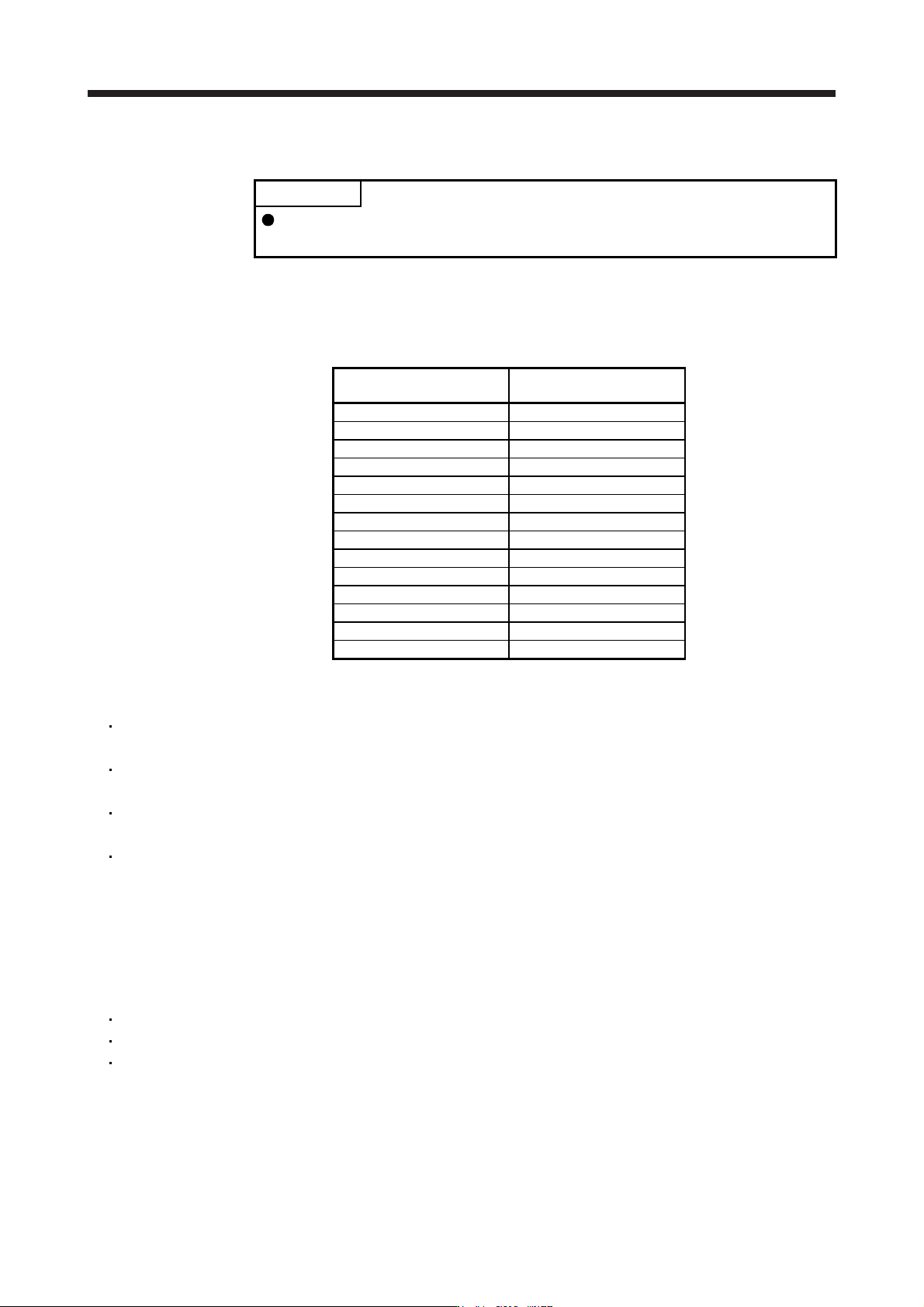
Multifunction regeneration
converter
Dedicated stand-alone
reactor
FR-XC-7.5K FR-XCL-7.5K
FR-XC-11K FR-XCL-11K
FR-XC-15K FR-XCL-15K
FR-XC-22K FR-XCL-22K
FR-XC-30K FR-XCL-30K
FR-XC-37K FR-XCL-37K
FR-XC-55K FR-XCL-55K
FR-XC-H7.5K FR-XCL-H7.5K
FR-XC-H11K FR-XCL-H11K
FR-XC-H15K FR-XCL-H15K
FR-XC-H22K FR-XCL-H22K
FR-XC-H30K FR-XCL-H30K
FR-XC-H37K FR-XCL-H37K
FR-XC-H55K FR-XCL-H55K
11.19.2 P
recautions
Set the FR-XC-(H) to the common bus regeneration mode by turning on switch 1 of the function
selecting switch (SW2).
Do not supply power to the main circuit power supply terminals (L1/L2/L3) of the servo amplifier. Doing
so may fail the servo amplifier and the FR-XC-(H).
Connect the polarities of the DC power supply between the FR-XC-(H) and the servo amplifier correctly.
Failing to do so may fail the FR-XC-(H) and the servo amplifier.
For 400 V, use the rated voltage and permissible fluctuation of the input power supply within the
following range.
Rated voltage: 3-phase 380 V to 480 V, 50 Hz/60 Hz
Permissible fluctuation: 3-phase 323 V to 528 V, 50 Hz/60 Hz
11.19.3 Servo amplifier settings
When using the FR-XC-(H), set the parameters as follows.
[Pr. PA02]: "_ _ 0 1"
[Pr. PA04]: "0 0 _ _"
[Pr. PC20]: "_ _ _ 1"
11. OPTIONS AND PERIPHERAL EQUIPMENT
11 - 119
11.19.4 Capac
ity selection
(1) Selection conditions
The multifunction regeneration converter FR-XC-(H) can be used with 200 V class servo amplifiers with
capacities of 100 W to 22 kW and 400 V class servo amplifiers with capacities of 600 W to 22 kW. Select
a multifunction regeneration converter based on the following selection conditions.
Number of servo amplifiers to be connected to one FR-XC-(H) is 10 or less
Total capacity of servo amplifiers [kW] ≤ Total capacity of servo amplifiers that can be connected to the
FR-XC-(H) [kW]
Effective value of the total servo motor output power [kW] ≤ Continuous output of the FR-XC-(H) [kW]
Maximum value of the total servo motor output power [kW] ≤ Instantaneous maximum output of the
FR-XC-(H) [kW]
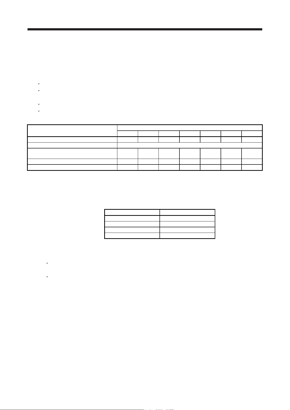
Item
FR-XC-(H)_
7.5K 11K 15K 22K 30K 37K 55K
Rated capacity [kW] 7.5 11 15 22 30 37 55
Maximum number of connectable servo amplifiers 10
Total capacity of connectable servo amplifiers
[kW] (Note)
3.5 (5.5) 5.5 (7.5) 7.5 (11) 22 30 37 55
Continuous output [kW] (Note) 3.5 (5.5) 5.5 (7.5) 7.5 (11) 18.5 22 30 45
Instantaneous maximum output [kW] 11.25 16.5 22.5 33 45 55.5 82.5
Note. Values in parentheses are when six servo amplifiers or less are connected.
(2)
Selection example
The following information explains how to select a multifunction regeneration converter to connect to the
servo amplifiers listed below.
Servo amplifier Servo motor
MR-J4-500B HG-SR502
MR-J4-500B HG-SR502
MR-J4-11KB HG-JR11K1M
MR-J4-22KB HG-JR22K1M
(a) Calc
ulate the running power and regenerative power from the servo motor speed and torque with the
following formulas.
For rotary servo motors
Running power and regenerative power [W] = Servo motor speed [r/min] × Torque [N•m]/9.55
For linear servo motors
Running power and regenerative power [W] = Servo motor speed [m/s] × Thrust [N]
(Running power is indicated by positive values, and regenerative power is indicted by negative
values.)
11. OPTIONS AND PERIPHERAL EQUIPMENT
11 - 120
(b) Calcu
late the total output power of the servo motors from the running power and regenerative power
of each servo motor.
-15 kW
-15 kW-15 kW
0.1 s
0.1 s
5 kW
0.1 s
40 kW
0.5 s
0.7 s
0.6 s
0.2 s0.3 s
0.1 s
0.1 s
0.2 s
0.1 s
0.1 s
0.1 s
0.1 s
0.1 s
0.1 s
5 kW
20 kW
20 kW
15 kW
-5 kW
10 kW
0.1 s
0.1 s
0.1 s
-5 kW
10 kW
15 kW
20 kW
MR-J4-500B/
HG-SR502
MR-J4-11KB/
HG-JR11K1M
MR-J4-22KB/
HG-JR22K1M
0.2 s
0.1 s
0.6 s
0.1 s 0.1 s
0.1 s-5 kW
10 kW
0.1 s 0.1 s
-5 kW
10 kW
MR-J4-500B/
HG-SR502
0.1 s
0.6 s
Power running
energy
Regenerative
power
Power running
energy
Regenerative
power
Power running
energy
Regenerative
power
Power running
energy
Regenerative
power
1.2 s per cycle
Power running
energy
Regenerative
power
Total output power
of servo motors
Total of each servo motor output
(c)
Select a multifunction regeneration converter based on the selection conditions.
Number of servo amplifiers: 4 ≤ 10
Number of servo amplifiers OK.
Total capacity of servo amplifiers [kW] = 5 kW + 5 kW + 11 kW + 22 kW = 43 kW
FR-XC-55K
Effective value of the total servo motor output power [kW]
=
(20
2
× 0.1 + 5
2
× 0.2 + 20
2
× 0.5 + 40
2
× 0.1 + 5
2
× 0.1 + (-15)
2
× 0.1)/1.2 = 18.93 kW
FR-XC-30K or more
Maximum value of the total servo motor output power [kW] = 40 kW
FR-XC-30K or more
Therefore, the multifunction regeneration converter selected should be the "FR-XC-55K".