sh030106u.pdf - 第401页
11. OPT ION S AND P ERI PHER AL EQU IPMENT 11 - 80 H ± 2. 5 W1 W ± 2.5 D2 D1 ± 1 PP 1 D or less (D3) 4-d mounting hole (Note 1) 6 Fig. 11.6 (Note 2) Servo amplifier P3 P4 FR-HEL-H 5 m or less P P1 Note 1. Use th is for g…
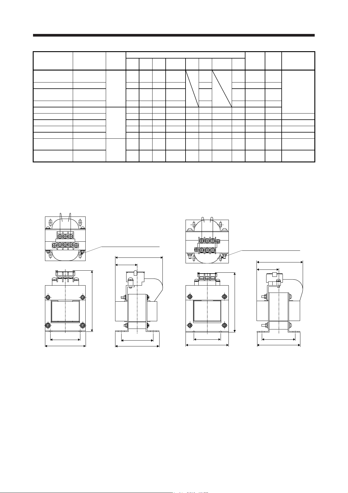
11. OPTIONS AND PERIPHERAL EQUIPMENT
11 - 79
Servo amplifier
Power factor
improving DC
reactor
Dimensions
Dimensions [mm]
Terminal
size
Mass
[kg]
Wire [mm
2
]
(Note 2)
W W1 H
D
(Note 1)
D1 D2 D3 d
MR-J4-10B(-RJ)
MR-J4-20B(-RJ)
FR-HEL-0.4K
Fig. 11.1
70 60 71 61
21
M4 M4 0.4
2 (AWG 14)
MR-J4-40B(-RJ) FR-HEL-0.75K 85 74 81 61 21 M4 M4 0.5
MR-J4-60B(-RJ)
MR-J4-70B(-RJ)
FR-HEL-1.5K 85 74 81 70 30 M4 M4 0.8
MR-J4-100B(-RJ) FR-HEL-2.2K 85 74 81 70 30 M4 M4 0.9
MR-J4-200B(-RJ) FR-HEL-3.7K
Fig. 11.2
77 55 92 82 66 57 37 M4 M4 1.5
MR-J4-350B(-RJ) FR-HEL-7.5K 86 60 113 98 81 72 43 M4 M5 2.5 3.5 (AWG 12)
MR-J4-500B(-RJ) FR-HEL-11K 105 64 133 112 92 79 47 M6 M6 3.3 5.5 (AWG 10)
MR-J4-700B(-RJ) FR-HEL-15K 105 64 133 115 97 84 48.5 M6 M6 4.1 8 (AWG 8)
MR-J4-11KB(-RJ) FR-HEL-15K 105 64 133 115 97 84 48.5 M6 M6 4.1 14 (AWG 6)
MR-J4-15KB(-RJ) FR-HEL-22K
Fig. 11.3
105 64 93 175 117 104
115
(Note 1)
M6 M10 5.6 22 (AWG 4)
MR-J4-22KB(-RJ) FR-HEL-30K 114 72 100 200 125 101
135
(Note 1)
M6 M10 7.8 38 (AWG 2)
Note 1. Maximum dimensions The dimension varies dependin
g
on the input/output lines.
2. Selection conditions of wire size are as follows.
600 V grade heat-resistant polyvinyl chloride insulated wire (HIV wire)
Construction condition: Sin
g
le wire set in midai
r
(2) 400 V class
W1
D2
W ± 2.5
H ± 2.5
D or less
(D3)
D1 ± 1
4-d mounting hole (Note 1)
PP1
Fig. 11.4
W1
W ± 2.5
D2
D1 ± 1
H ± 2.5
PP1
D or less
(D3)
4-d mounting hole (Note 1)
Fig. 11.5
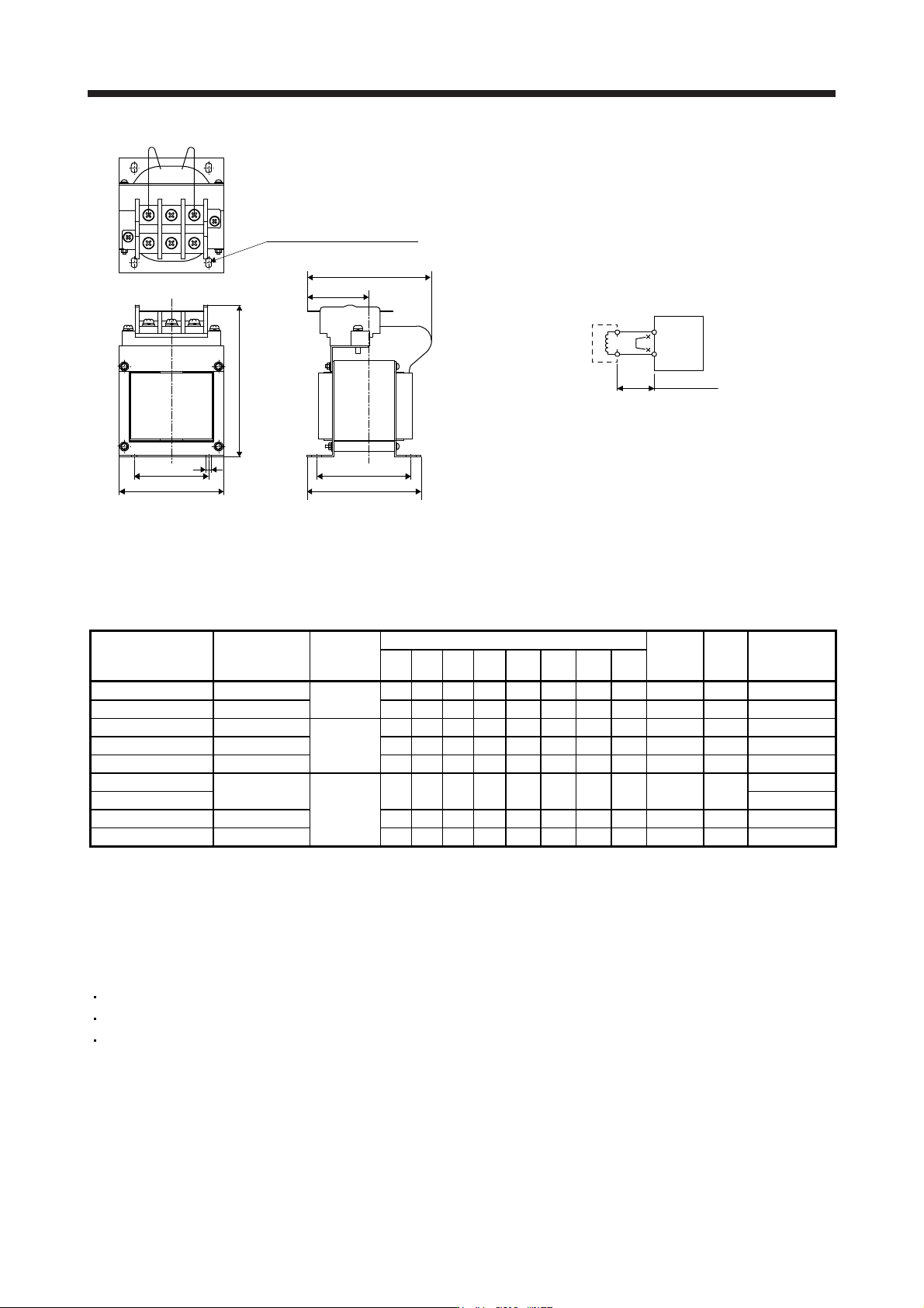
11. OPTIONS AND PERIPHERAL EQUIPMENT
11 - 80
H ± 2.5
W1
W ± 2.5
D2
D1 ± 1
PP1
D or less
(D3)
4-d mounting hole (Note 1)
6
Fig. 11.6
(Note 2)
Servo amplifier
P3
P4
FR-HEL-H
5 m or less
P
P1
Note 1. Use this for
g
roundin
g
.
2. When usin
g
the power factor improvin
g
DC reactor, remove the short bar across P3 and P4.
Servo amplifier
Power factor
improving DC
reactor
Dimensions
Dimensions [mm]
Terminal
size
Mass
[kg]
Wire [mm
2
]
(Note)
WW1H D D1D2D3 d
MR-J4-60B4(-RJ) FR-HEL-H1.5K
Fig. 11.4
66 50 100 80 74 54 37 M4 M3.5 1.0 2 (AWG 14)
MR-J4-100B4(-RJ) FR-HEL-H2.2K 76 50 110 80 74 54 37 M4 M3.5 1.3 2 (AWG 14)
MR-J4-200B4(-RJ) FR-HEL-H3.7K 86 55 120 95 89 69 45 M4 M4 2.3 2 (AWG 14)
MR-J4-350B4(-RJ) FR-HEL-H7.5K Fig. 11.5 96 60 128 105 100 80 50 M5 M4 3.5 2 (AWG 14)
MR-J4-500B4(-RJ) FR-HEL-H11K 105 75 137 110 105 85 53 M5 M5 4.5 3.5 (AWG 12)
MR-J4-700B4(-RJ)
FR-HEL-H15K
Fig. 11.6
105 75 152 125 115 95 62 M5 M6 5.0
5.5 (AWG 10)
MR-J4-11KB4(-RJ) 8 (AWG 8)
MR-J4-15KB4(-RJ) FR-HEL-H22K 133 90 178 120 95 75 53 M5 M6 6.0 8 (AWG 8)
MR-J4-22KB4(-RJ) FR-HEL-H30K 133 90 178 120 100 80 56 M5 M6 6.5 14 (AWG 6)
Note. Selection conditions of wire size are as follows.
Wire type: 600 V grade heat-resistant polyvinyl chloride insulated wire (HIV wire)
Construction condition: Sin
g
le wire set in midai
r
11.12 Power factor improving AC reactors
The following shows the advantages of using power factor improving AC reactor.
It improves the power factor by increasing the form factor of the servo amplifier's input current.
It decreases the power supply capacity.
The input power factor is improved to about 80%.
When using power factor improving reactors for two servo amplifiers or more, be sure to connect a power
factor improving reactor to each servo amplifier. If using only one power factor improving reactor, enough
improvement effect of phase factor cannot be obtained unless all servo amplifiers are operated.
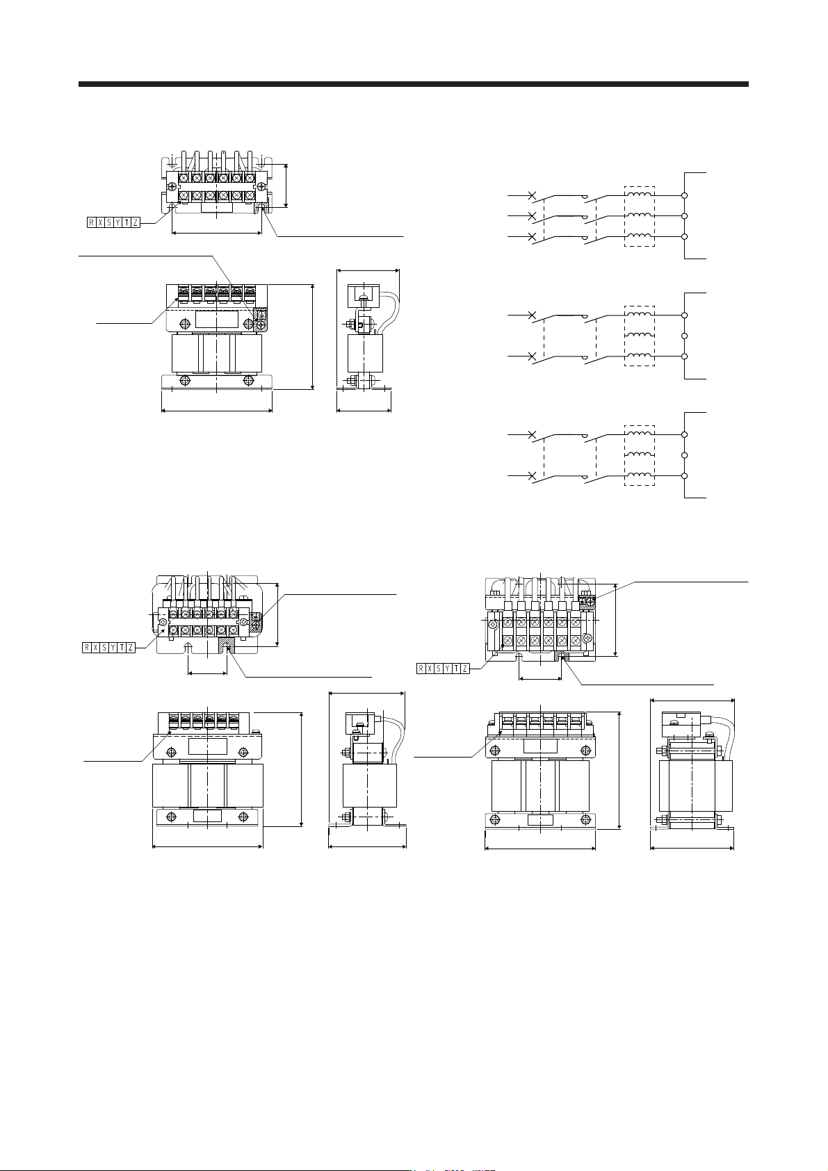
11. OPTIONS AND PERIPHERAL EQUIPMENT
11 - 81
(1) 200 V class/100 V class
D2
W1
W
H
D1
D
Terminal layout
Installation hole for 4-d
(near right side, varnish removed)
Earth (ground) terminal
W
ire the earthing (grounding) cable
t
o the earth (ground) terminal
Terminal block
(with cover)
Fig. 11.7
Y
Z
S
T
Y
Z
S
T
MCMCCB
MCMCCB
FR-HAL
XR
L1
L2
L3
FR-HAL
XR
L1
L2
L3
Y
Z
S
T
MCMCCB
FR-HAL
XR
L1
L2
Servo amplifier
3-phase 200 V class
3-phase
2
00 V AC to
2
40 V AC
Servo amplifier
1-phase 200 V class
(Note)
1-phase
2
00 V AC to
2
40 V AC
Servo amplifier
1-phase 100 V class
1-phase
100 V AC to
120 V AC
Unassigned
Note. For 1-phase 200 V AC to 240 V AC, connect the power
supply to L1 and L3. Leave L2 open.
D2
W1
W
H
D1
D
Terminal layout
Installation hole for 4-d
(near right side, varnish removed)
Earth (ground) terminal
Wire the earthing (grounding)
cable to the earth (ground)
terminal
Terminal block
(with cover)
Fig. 11.8
W1
D2
W
H
D1
MAX D
Terminal layout
Earth (ground) terminal
Wire the earthing (grounding)
cable to the earth (ground)
terminal
Terminal block
(with cover)
Installation hole for 4-d
(near right side, varnish removed)
Fig. 11.9