sh030106u.pdf - 第534页
16. FULLY CLOSE D L OOP SYS TEM 16 - 9 16.2.4 MR-J 4FCCBL 03M b ranch cabl e Use MR-J4FCC BL03M br anc h cable to c onnect the rotar y encoder an d the load- side encod er to C N2 connector. When fabr icating the br anch…
16. FULLY CLOSED LOOP SYSTEM
16 - 8
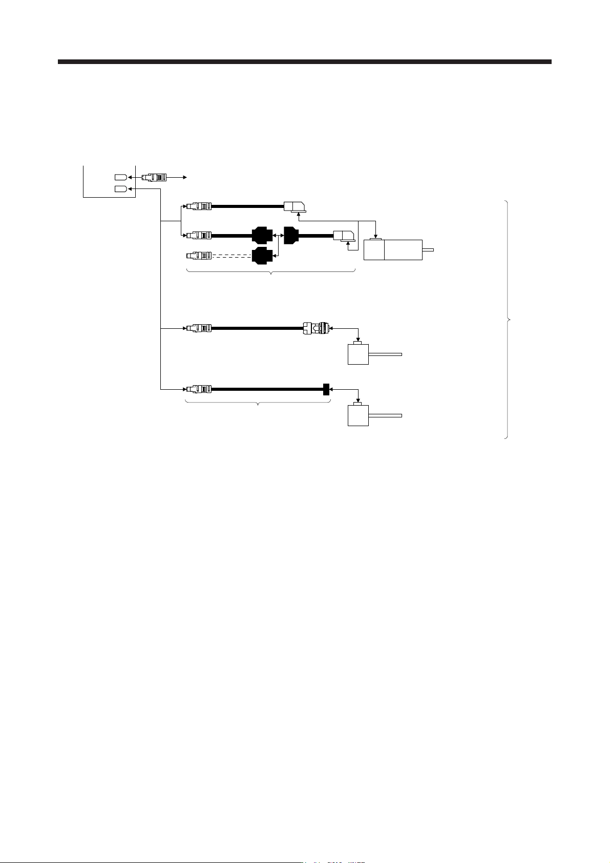
(b) MR-J4-_B_-RJ servo amplifier
For the MR-J4-_B_-RJ servo amplifier, a rotary encoder can be connected without the branch cable
shown in the above (a). In addition, a four-wire type or A/B/Z-phase differential output rotary encoder
can also be used.
CN2
CN2L
Q170ENCCBL_M-A
HG-KR
HG-MR
Servo amplifier
Encoder of rotary servo motor
Encoder cable
(Refer to "Servo Motor Instruction Manual (Vol. 3)".)
Load-side
encoder
Servo motor
Synchronous encoder Q171ENC-W8
Encoder cable
(Refer to "Linear Encoder Instruction Manual".)
A/B/Z-phase differential output rotary
encoder (Note)
Note.
A
/B/Z-phase differential output rotary encoders with the same specifications as A/B/Z-phase differential output linear encoders can
be used as load-side encoders. Refer to "Linear Encoder Instruction Manual".
16. FULLY CLOSED LOOP SYSTEM
16 - 9
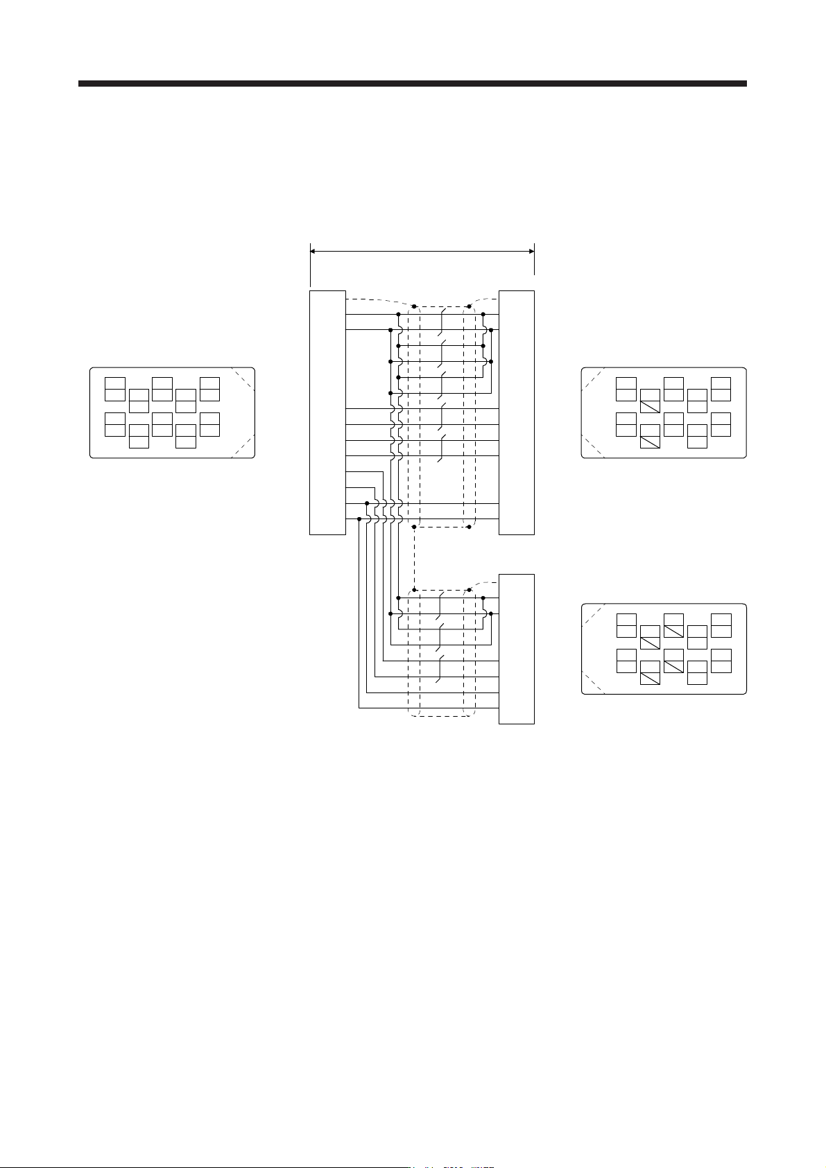
16.2.4 MR-J4FCCBL03M branch cable
Use MR-J4FCCBL03M branch cable to connect the rotary encoder and the load-side encoder to CN2
connector.
When fabricating the branch cable using MR-J3THMCN2 connector set, refer to "Linear Encoder Instruction
Manual".
LG
View seen from wiring side.
4
MRR
2
LG
8
6
1
P5
5
10
3
MR
7
9
THM2
THM1
MXR
SEL
THM2
THM1
SEL
MX
BAT
SD
3
4
1
CN2 MOTOR
Plate
(Note 1) (Note 2)
0.3 m
MR
P5
MRR
SD
MR
P5
MRR
3
4
1
Plate
View seen from wiring side.
4
MRR
2
8
6
1
P5
5
10
3
MR
7
9
View seen from wiring side.
4
2
8
6
15
10
37
9
BAT
2
THM2 6
7
MX
LG LG2
MXR 8
BAT
SEL
9
10
5THM1 5 THM1
6 THM2
9 BAT
10 SEL
SCALE
(Note 2)
P5
SD
SEL
LG
1
2
10
Plate
4 MXR
BAT9
3MX
BAT
SEL
LG
P5
MXR
MX
Note 1. Receptacle: 36210-0100PL, shell kit: 36310-3200-008
(
3M
)
2. Plu
g
: 36110-3000FD, shell kit: 36310-F200-008
(
3M
)
16. FULLY CLOSED LOOP SYSTEM
16 - 10
16.3 Operation and functions
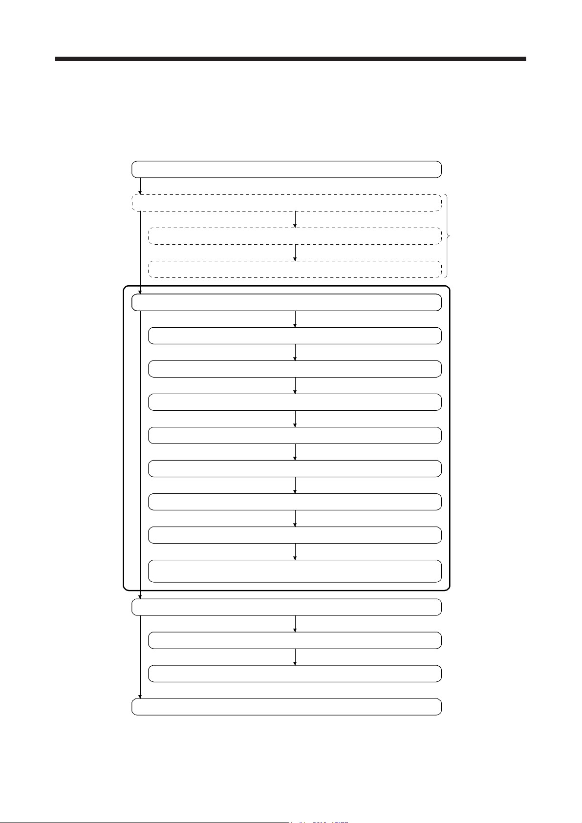
16.3.1 Startup
(1) Startup procedure
Start up the fully closed loop system in the following procedure.
Positioning operation check using the controller (Refer to section 16.3.3.)
Positioning operation check using MR Configurator2
Gain adjustment
Completion of installation and wiring
Positioning operation check using MR Configurator2
Adjustment and operation check in semi closed loop system
Gain adjustment
Adjustment and operation check in fully closed loop system
Selection of fully closed loop system (Refer to (2) in this section.)
Selection of load-side encoder communication system (Refer to (3) in this section.)
Adjustment of dual feedback switching filter.
(for dual feedback control) (Refer to (5) in this section.)
Setting of load-side encoder polarity (Refer to (4) in this section.)
Home position return operation (Refer to section 16.3.2.)
Positioning operation
Completion of fully closed loop system startup
Check that the servo
equipment is normal.
Do as necessary.
Setting of load-side encoder electronic gear (Refer to (5) in this section.)
Confirmation of load-side encoder position data (Refer to (6) in this section.)