sh030106u.pdf - 第340页
11. OPT ION S AND P ERI PHER AL EQU IPMENT 11 - 19 (3) MR-J4-11KB(-RJ) to MR-J4-22KB(-RJ)/MR-J4 -11KB4(-RJ) to MR-J 4-22 KB4(-R J) (when usin g the supplied regener ativ e resist or) CAUTION The regener ative r esist or …
11. OPTIONS AND PERIPHERAL EQUIPMENT
11 - 18
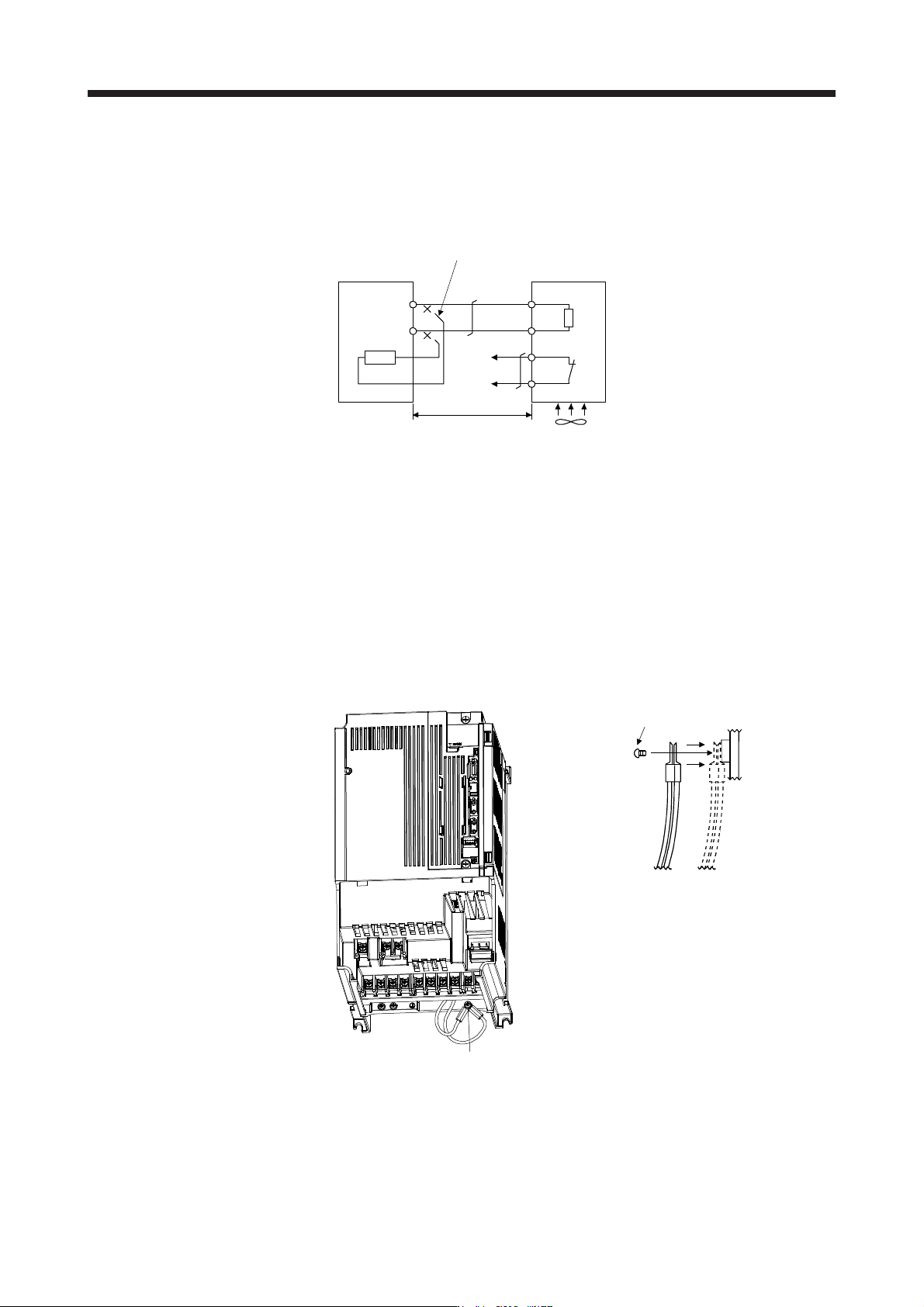
(2) MR-J4-500B4(-RJ)/MR-J4-700B(-RJ)/MR-J4-700B4(-RJ)
Always remove the wiring (across P+ to C) of the servo amplifier built-in regenerative resistor and fit the
regenerative option across P+ to C. G3 and G4 are thermal sensor's terminals. Between G3 and G4 is
opened when the regenerative option overheats abnormally.
Always remove the wiring (across P+ to C) of the servo
amplifier built-in regenerative resistor.
P+
C
G4
G3
C
P
Regenerative option
5 m or less
Servo amplifier
(Note 2)
Cooling fan
(Note 1)
Note 1. When using the MR-RB51, MR-RB34-4, MR-RB54-4, MR-RB3U-4, or MR-RB5U-
4, forcibl
y
cool it with a coolin
g
fan
(
1.0 m
3
/
min or more, 92 mm × 92 mm
)
.
2. Make up a sequence which will switch off the magnetic contactor when abnormal
heating occurs.
G3-G4 contact specifications
Maximum voltage: 120 V AC/DC
Maximum current: 0.5 A/4.8 V DC
Maximum capacit
y
: 2.4 V
A
When using the regenerative option, remove the servo amplifier's built-in regenerative resistor wires
(across P+ to C), fit them back to back, and secure them to the frame with the accessory screw as
shown below.
Built-in regenerative resistor
lead terminal fixing screw
Accessory screw
11. OPTIONS AND PERIPHERAL EQUIPMENT
11 - 19
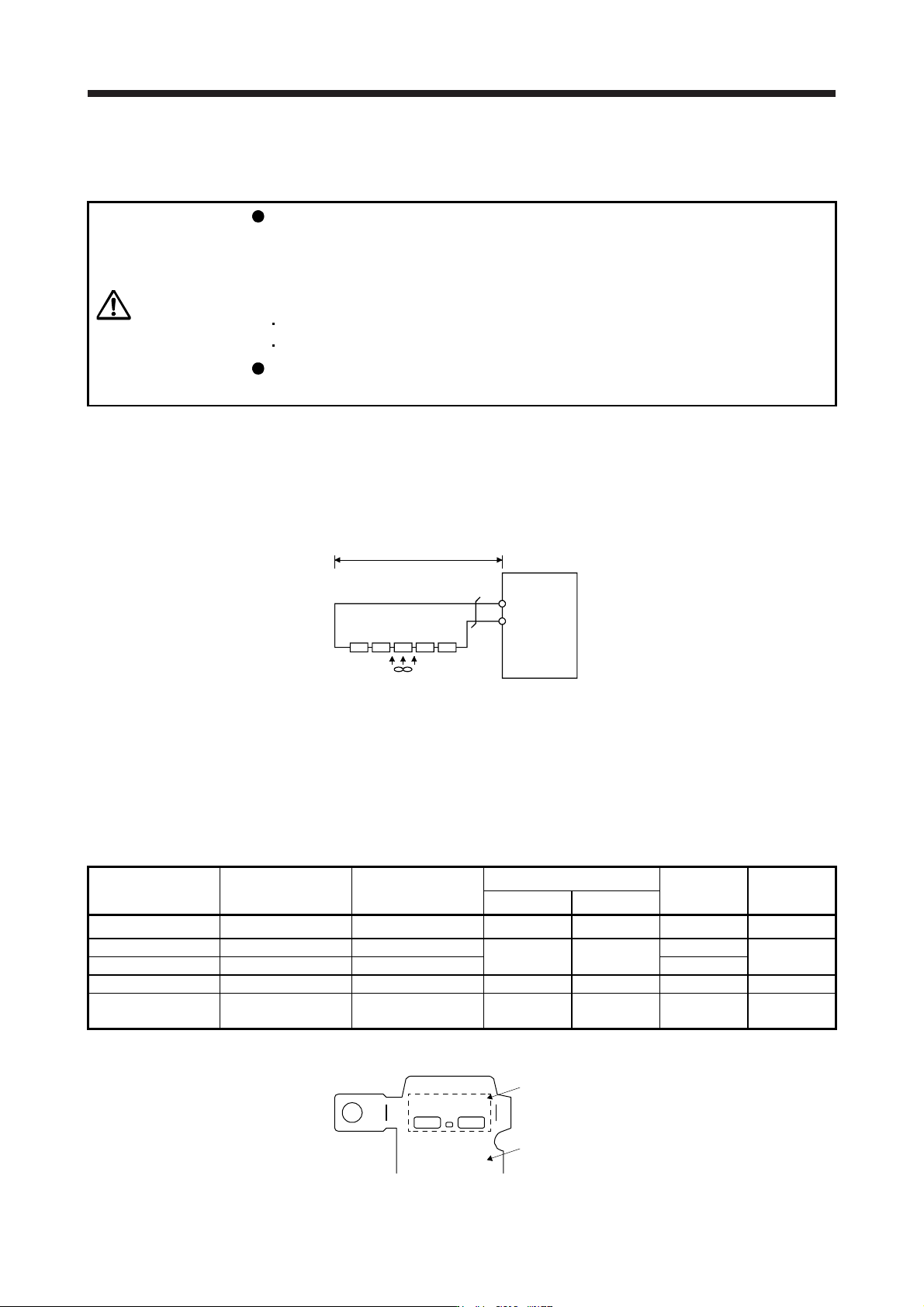
(3) MR-J4-11KB(-RJ) to MR-J4-22KB(-RJ)/MR-J4-11KB4(-RJ) to MR-J4-22KB4(-RJ) (when using the
supplied regenerative resistor)
CAUTION
The regenerative resistor supplied with 11 kW to 22 kW servo amplifiers does not
have a protective cover. Touching the resistor (including wiring/screw hole area)
may cause a burn injury and electric shock. Even if the power was shut-off, be
careful until the bus voltage discharged and the temperature decreased because
of the following reasons.
It may cause a burn injury due to very high temperature without cooling.
It may cause an electric shock due to charged capacitor of the servo amplifier.
Do not use servo amplifiers with external regenerative resistors other than the
combinations specified below. Otherwise, it may cause a fire.
When using the regenerative resistors supplied to the servo amplifier, the specified number of resistors
(4 or 5 resistors) must be connected in series. If they are connected in parallel or in less than the
specified number, the servo amplifier may become faulty and/or the regenerative resistors burn.
Install the resistors at intervals of about 70 mm. Cooling the resistors with two cooling fans (1.0 m
3
/min
or more, 92 mm × 92 mm) improves the regeneration capability. In this case, set "_ _ F A" in [Pr. PA02].
P+
C
Servo amplifier
Cooling fan
(Note) Series connection
5 m or less
Note. The number of resistors connected in series depends on the resistor type. The
thermal sensor is not mounted on the attached regenerative resistor. An abnormal
heating of resistor may be generated at a regenerative circuit failure. Install a thermal
sensor near the resistor and establish a protective circuit to shut off the main circuit
power supply when abnormal heating occurs. The detection level of the thermal
sensor varies according to the settings of the resistor. Set the thermal sensor in the
most appropriate position on your design basis, or use the thermal sensor built-in
re
g
enerative option.
(
MR-RB5R, MR-RB9F, MR-RB9T, MR-RB5K-4, or MR-RB6K-4
)
Servo amplifier Regenerative resistor Symbol (Note)
Regenerative power [W]
Resultant
resistance [Ω]
Number of
resistors
Normal Cooling
MR-J4-11KB(-RJ) GRZG400-0.8Ω GR400 R80K 500 800 3.2
4
MR-J4-15KB(-RJ) GRZG400-0.6Ω GR400 R60K
850 1300
3
5
MR-J4-22KB(-RJ) GRZG400-0.5Ω GR400 R50K 2.5
MR-J4-11KB4(-RJ) GRZG400-2.5Ω GR400 2R5K 500 800 10
4
MR-J4-15KB4(-RJ)
MR-J4-22KB4(-RJ)
GRZG400-2Ω GR400 2R0K 850 1300 10 5
Note. The followin
g
shows an indication example of s
y
mbol.
GR400 R80K
Symbol
Regenerative resistor
11. OPTIONS AND PERIPHERAL EQUIPMENT
11 - 20
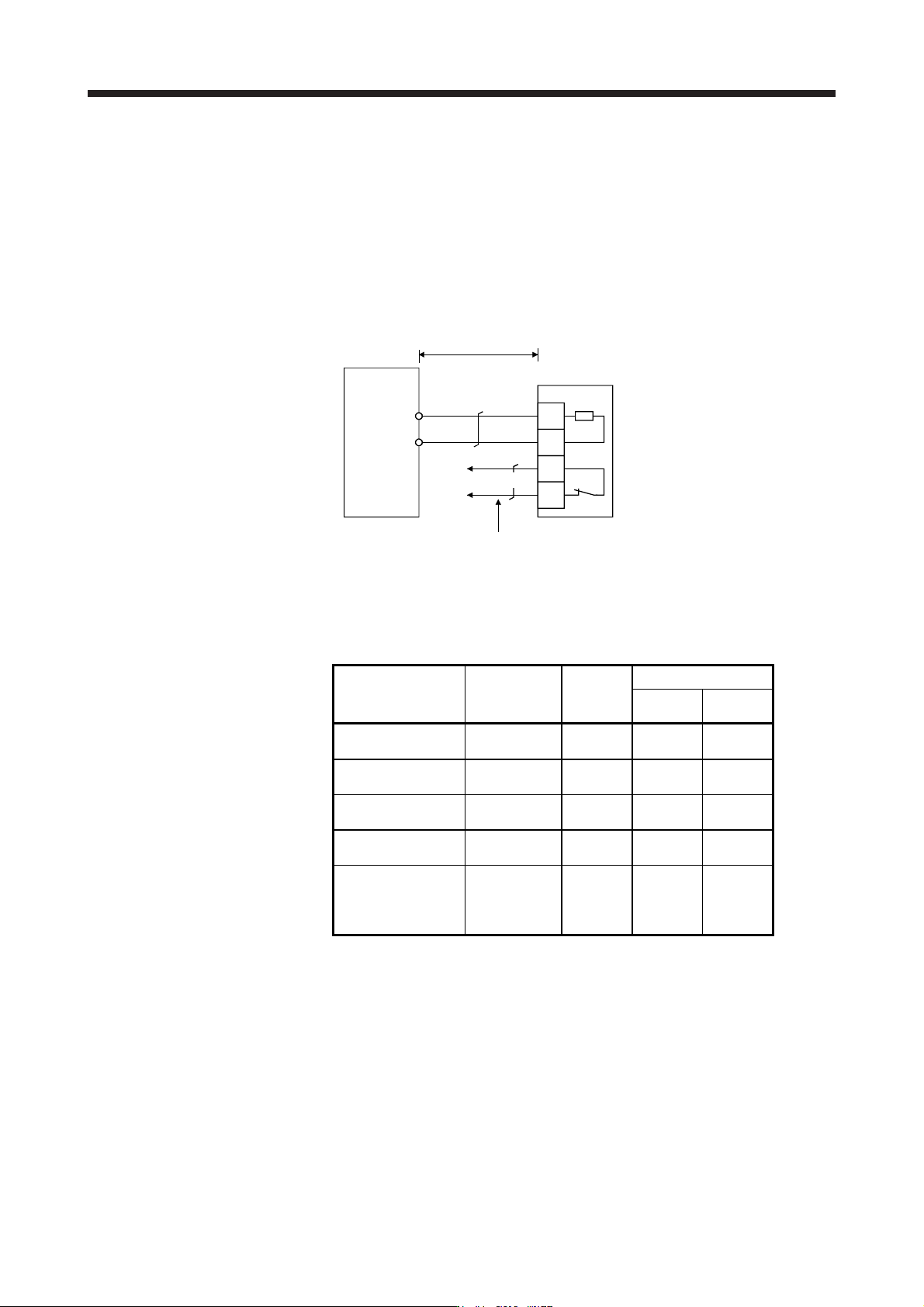
(4) MR-J4-11KB-PX to MR-J4-22KB-PX/MR-J4-11KB-RZ to MR-J4-22KB-RZ/MR-J4-11KB4-PX to MR-J4-
22KB4-PX/MR-J4-11KB4-RZ to MR-J4-22KB4-RZ (when using the regenerative option)
The MR-J4-11KB-PX to MR-J4-22KB-PX, MR-J4-11KB-RZ to MR-J4-22KB-RZ, MR-J4-11KB4-PX to
MR-J4-22KB4-PX, and MR-J4-11KB4-RZ to MR-J4-22KB4-RZ servo amplifiers are not supplied with
regenerative resistors. When using any of these servo amplifiers, always use the regenerative option
MR-RB5R, MR-RB9F, MR-RB9T, MR-RB5K-4, and MR-RB6K-4.
Cooling the regenerative option with cooling fans improves regenerative capability. G3 and G4 are
thermal sensor's terminals. Between G3 and G4 is opened when the regenerative option overheats
abnormally.
Regenerative option
Configure up a circuit which shuts off main
circuit power when thermal protector operates.
Servo amplifier
C
P+
5 m or less
(Note)
P
C
G3
G4
Note. G3-G4 contact specifications
Maximum voltage: 120 V AC/DC
Maximum current: 0.5 A/4.8 V DC
Maximum capacit
y
: 2.4 V
A
Servo amplifier
Regenerative
option
Resistance
[Ω]
Regenerative power [W]
Without
cooling fans
With cooling
fans
MR-J4-11KB-PX
MR-J4-11KB-RZ
MR-RB5R 3.2 500 800
MR-J4-15KB-PX
MR-J4-15KB-RZ
MR-RB9F 3 850 1300
MR-J4-22KB-PX
MR-J4-22KB-RZ
MR-RB9T 2.5 850 1300
MR-J4-11KB4-PX
MR-J4-11KB4-RZ
MR-RB5K-4 10 500 800
MR-J4-15KB4-PX
MR-J4-15KB4-RZ
MR-J4-22KB4-PX
MR-J4-22KB4-RZ
MR-RB6K-4 10 850 1300