sh030106u.pdf - 第313页
10. CHA RACT ERISTI CS 10 - 8 10.3 Dynam ic brak e char acteris tics CAUTION The coasti ng dis tance is a t heoretic ally c alculate d val ue that does not consid er factors suc h as fricti on. The calculated valu e will…

10. CHARACTERISTICS
10 - 7
(2) Heat dissipation area for an enclosed type cabinet
The enclosed type cabinet (hereafter called the cabinet) which will contain the servo amplifier should be
designed to ensure that its temperature rise is within +10 °C at the ambient temperature of 40 °C. (With
an approximately 5 °C safety margin, the system should operate within a maximum 55 °C limit.) The
necessary cabinet heat dissipation area can be calculated by equation 10.1.
A =
K •
P
T
················································································································· (10.1)
A: Heat dissipation area [m
2
]
P: Loss generated in the cabinet [W]
Δ
T: Difference between internal and ambient temperatures [°C]
K: Heat dissipation coefficient [5 to 6]
When calculating the heat dissipation area with equation 10.1, assume that P is the sum of all losses
generated in the cabinet. Refer to table 10.1 for heat generated by the servo amplifier. "A" indicates the
effective area for heat dissipation, but if the cabinet is directly installed on an insulated wall, that extra
amount must be added to the cabinet's surface area. The required heat dissipation area will vary with the
conditions in the cabinet. If convection in the cabinet is poor and heat builds up, effective heat
dissipation will not be possible. Therefore, arrangement of the equipment in the cabinet and the use of a
cooling fan should be considered. Table 10.1 lists the cabinet dissipation area for each servo amplifier
(guideline) when the servo amplifier is operated at the ambient temperature of 40 °C under rated load.
(Outside the cabinet) (Inside the cabinet)
Air flow
Fig. 10.2 Temperature distribution in an enclosed type cabinet
When air flows along the outer wall of the cabinet, effective heat exchange will be possible, because the
temperature slope inside and outside the cabinet will be steeper.
10. CHARACTERISTICS
10 - 8
10.3 Dynamic brake characteristics
CAUTION
The coasting distance is a theoretically calculated value that does not consider
factors such as friction. The calculated value will be longer than the actual
distance. If the braking distance is not longer than the calculated value, a moving
part may crash into the stroke end, causing a dangerous situation. Install an anti-
crash mechanism such as an air brake or an electric/mechanical stopper such as
a shock absorber to reduce the shock of moving parts.
POINT
Do not use dynamic brake to stop in a normal operation as it is the function to
stop in emergency.
For a machine operating at the recommended load to motor inertia ratio or less,
the estimated number of usage times of the dynamic brake is 1000 times while
the machine decelerates from the rated speed to a stop once in 10 minutes.
Be sure to enable EM1 (Forced stop 1) after servo motor stops when using EM1
(Forced stop 1) frequently in other than emergency.
Servo motors for MR-J4 may have the different coasting distance from that of
the previous model.
The electronic dynamic brake operates in the initial state for the HG series servo
motors of 600 W or smaller capacity. The time constant "τ" for the electronic
dynamic brake will be shorter than that of normal dynamic brake. Therefore,
coasting distance will be shorter than that of normal dynamic brake. For how to
set the electronic dynamic brake, refer to [Pr. PF06] and [Pr. PF12].
10. CHARACTERISTICS
10 - 9
10.3.1 Dynamic brake operation
(1) Calculation of coasting distance
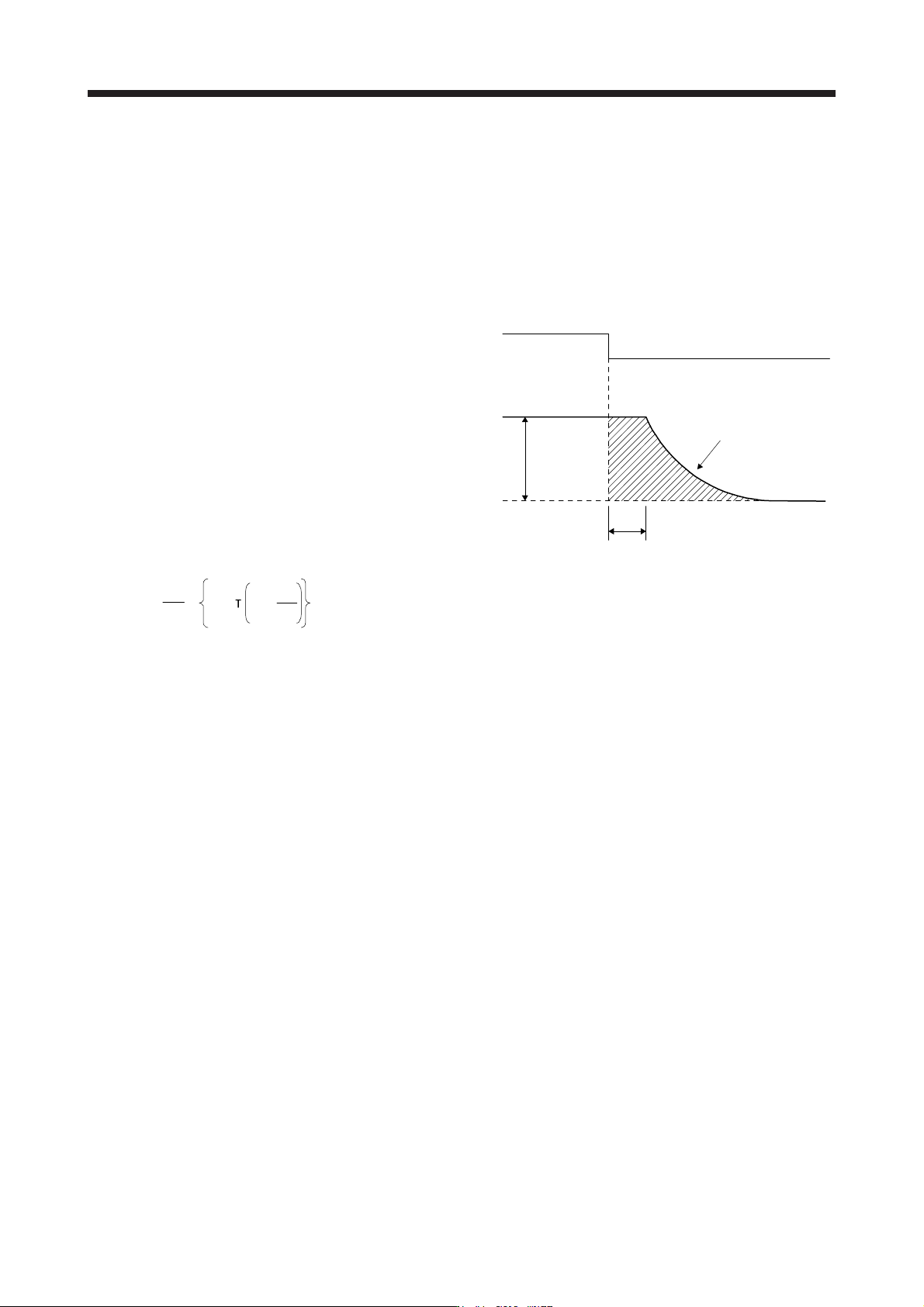
Fig. 10.3 shows the pattern in which the servo motor comes to a stop when the dynamic brake is
operated. Use equation 10.2 to calculate an approximate coasting distance to a stop. The dynamic brake
time constant τ varies with the servo motor and machine operation speeds. (Refer to (2) (a), (b) in this
section.)
A working part generally has a friction force. Therefore, actual coasting distance will be shorter than a
maximum coasting distance calculated with the following equation.
V
0
OFF
ON
Machine speed
t
e
Time
EM1 (Forced stop 1)
Dynamic brake
time constant τ
Fig. 10.3 Dynamic brake operation diagram
L
max
=
60
V
0
•
t
e
+
J
M
1 +
J
L
··························································································· (10.2)
L
max
: Maximum coasting distance ······················································································ [mm]
V
0
: Machine's fast feed speed ····················································································· [mm/min]
J
M
: Moment of inertia of the servo motor ··································································· [× 10
-4
kg•m
2
]
J
L
: Load moment of inertia converted into equivalent value on servo motor shaft ·············· [× 10
-4
kg•m
2
]
τ: Dynamic brake time constant ···························································································· [s]
t
e
: Delay time of control section ···························································································· [s]
For the servo amplifier of 7 kW or less, there is internal relay delay time of about 10 ms. For the servo
amplifier of 11 kW to 22 kW, there is delay caused by magnetic contactor built into the external
dynamic brake (about 50 ms) and delay caused by the external relay.