sh030106u.pdf - 第374页
11. OPT ION S AND P ERI PHER AL EQU IPMENT 11 - 53 11.6 Junc tion ter minal block PS7DW-2 0V14B- F (rec omme nded) (1) Usage Always use the junctio n ter minal block ( PS7W- 20V1 4B-F (Toho T ec hno logy)) wi th the opti…
11. OPTIONS AND PERIPHERAL EQUIPMENT
11 - 52
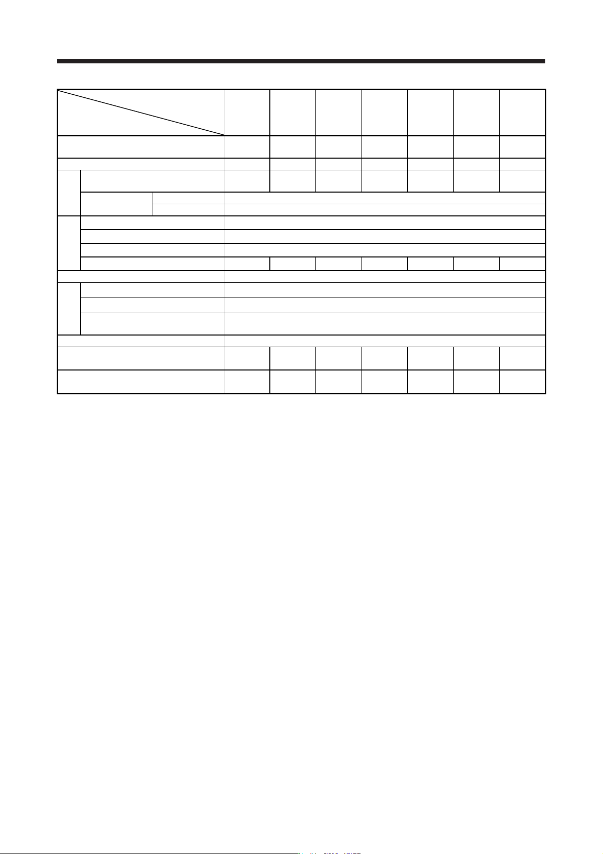
Power regeneration
common converter
FR-CV-H_
Item
7.5K 11K 15K 22K 30K 37K 55K
Total of connectable servo amplifier
capacities
[kW] 3.75 5.5 7.5 11 15 185 27.5
Maximum servo amplifier capacity [kW] 3.5 5 7 11 15 15 22
Output
Total of connectable servo
motor rated currents
[A] 17 23 31 43 57 71 110
Regenerative
braking torque
Short-time rating Total capacity of applicable servo motors, 300% torque, 60 s (Note 1)
Continuous rating 100% torque
Power supply
Rated input AC voltage/frequency 3-phase 380 V AC to 480 V AC, 50 Hz/60 Hz
Permissible AC voltage fluctuation 3-phase 323 V AC to 528 V AC, 50 Hz/60 Hz
Permissible frequency fluctuation ±5%
Power supply capacity (Note 2) [kVA] 17 20 28 41 52 66 100
IP rating (JEM 1030), cooling method Open type (IP00), forced cooling
Environment
Ambient temperature -10 °C to 50 °C (non-freezing)
Ambient humidity 5 %RH to 90 %RH (non-condensing)
Ambience
Indoors (no direct sunlight), free from corrosive gas, flammable gas,
oil mist, dust, and dirt
Altitude, vibration resistance 1000 m or less above sea level, 5.9 m/s
2
Molded-case circuit breaker or earth-leakage
current breaker
30AF
15A
30AF
20A
30AF
30A
50AF
50A
60AF
60A
100AF
75A
100AF
100A
Magnetic contactor
S-N20
S-T21
S-N20
S-T21
S-N20
S-T21
S-N25
S-T25
S-N35
S-T35
S-N50
S-T50
S-N65
S-T65
Note 1. This is the time when the protective function of the FR-CV-(H) is activated. The protective function of the servo amplifier is
activated in the time indicated in section 10.1.
2. The specified value is the power supply capacity of FR-CV-(H). The total power supply capacities of the connected servo
amplifiers are actuall
y
required.
11. OPTIONS AND PERIPHERAL EQUIPMENT
11 - 53
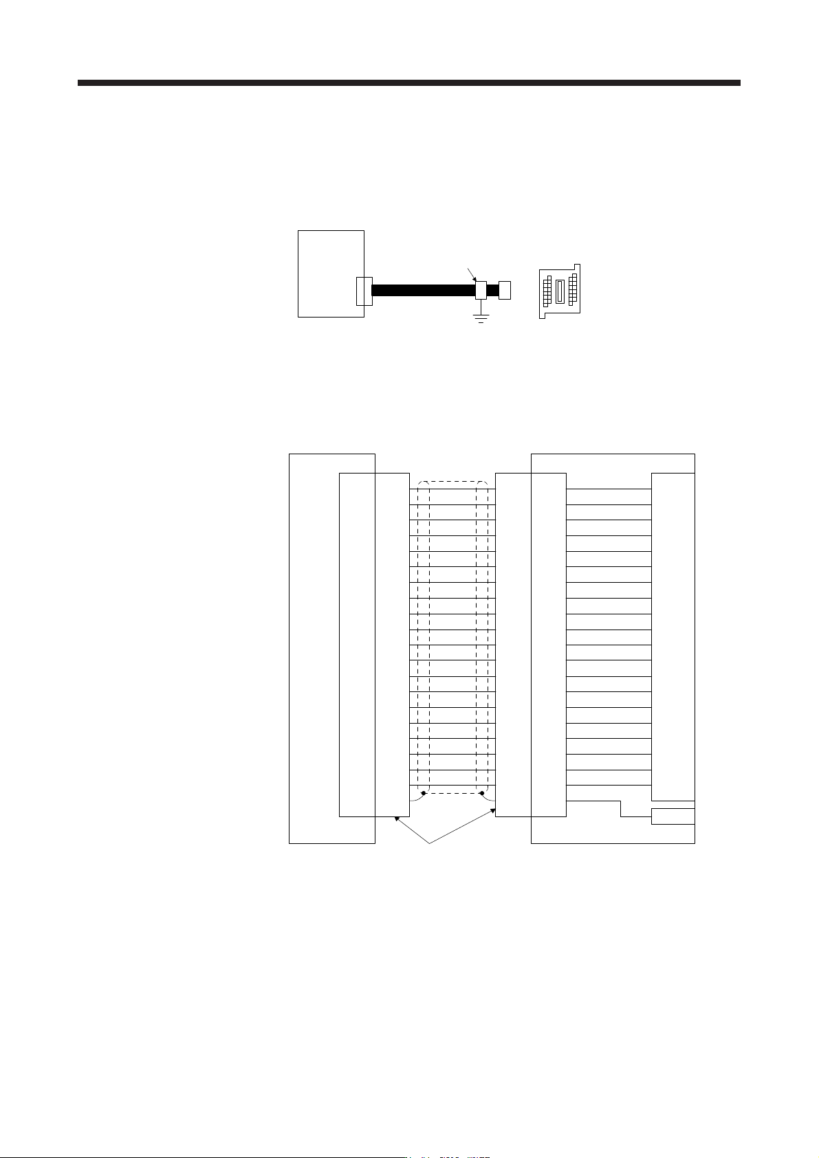
11.6 Junction terminal block PS7DW-20V14B-F (recommended)
(1) Usage
Always use the junction terminal block (PS7W-20V14B-F (Toho Technology)) with the option cable (MR-
J2HBUS_M) as a set. A connection example is shown below.
Junction terminal bloc
k
PS7DW-20V14B-F
CN3
MR-J2HBUS_M
Servo amplifie
r
Cable clamp
(AERSBAN-ESET)
Ground the junction terminal block cable on the junction terminal block side with the supplied cable
clamp fitting (AERSBAN-ESET). For the use of the cable clamp fitting, refer to section 11.14, (2) (c).
(2) Connection of MR-J2HBUS_M cable and junction terminal block
LG
DI1
1
2
DOCOM
MO1
3
4
LZ 8
LB 7
9
SD
Shell
(Note) MR-J2HBUS_M
INP
5
6
10DICOM
DICOM
LA
LG
DI2
11
12
MBR
MO2
13
14
LZR 18
LBR 17
19DI3
15
16
20EM2
ALM
LAR
Shell Shell Shell
1
2
3
4
8
7
9
5
6
10
11
12
13
14
18
17
19
15
16
20
1
2
3
4
8
7
9
5
6
10
11
12
13
14
18
17
19
15
16
20
1
2
3
4
8
7
9
5
6
10
11
12
13
14
18
17
19
15
16
20
LG
DI1
DOCOM
MO1
LZ
LB
SD
INP
DICOM
DICOM
LA
LG
DI2
MBR
MO2
LZR
LBR
DI3
EM2
ALM
LAR
E
Servo amplifier
CN3
Junction terminal block
PS7DW-20V14B-F
Connector: 52316-2019 (Molex)
Shell kit: 52370-2070 (Molex)
CN
Terminal block
1
2
3
4
8
7
9
5
6
10
11
12
13
14
18
17
19
15
16
20
Note. Symbol indicating cable length is put in _.
05: 0.5 m
1: 1 m
5: 5 m
11. OPTIONS AND PERIPHERAL EQUIPMENT
11 - 54
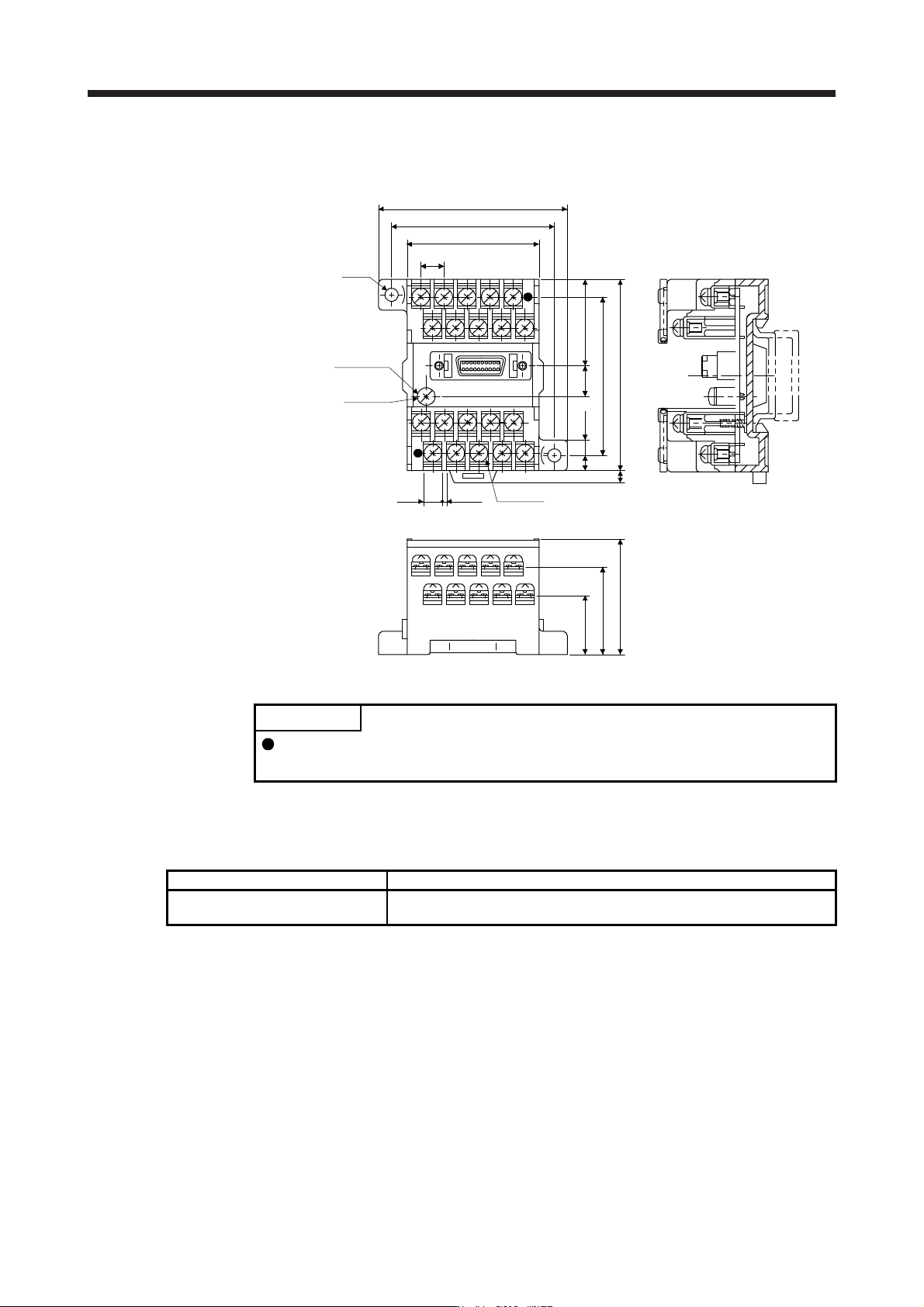
(3) Dimensions of junction terminal block
[Unit: mm]
M3 × 6L
M3 × 5L
36.5
27.8
18.8
7.62
44.11
54
63
φ4.5
4.5
5
4
60
50
9.3 27
TB.E (φ6)
1.426.2
11.7 MR Configurator2
POINT
The MR-J4-_B_-RJ servo amplifier is supported with software version 1.19V or
later.
11.7.1 Engineering software
The following engineering software is available with this servo amplifier.
Engineering software Installation guide
MR Configurator2 SW1DNC-MRC2-_
MR Configurator2 SW1DNC-MRC2-_ INSTALLATION GUIDE
(IB(NA)0300163ENG)
For the engineering software specifications and system configuration, refer to the installation guide.