sh030106u.pdf - 第146页
5. PARAMETE RS 5 - 1 5. PARAMET ERS CAUTION Never make a drast ic adj ustment or cha nge to t he paramet er valu es as doin g so will make th e oper ation unstabl e. Do not chan ge the paramet er settin gs as des crib ed…

4. STARTUP
4 - 20
MEMO
5. PARAMETERS
5 - 1
5. PARAMETERS
CAUTION
Never make a drastic adjustment or change to the parameter values as doing so
will make the operation unstable.
Do not change the parameter settings as described below. Doing so may cause
an unexpected condition, such as failing to start up the servo amplifier.
Changing the values of the parameters for manufacturer setting
Setting a value out of the range
Changing the fixed values in the digits of a parameter
When you write parameters with the controller, make sure that the control axis No.
of the servo amplifier is set correctly. Otherwise, the parameter settings of another
axis may be written, possibly causing the servo amplifier to be an unexpected
condition.
POINT
When you connect the amplifier to a servo system controller, servo parameter
values of the servo system controller will be written to each parameter.
Setting may not be made to some parameters and their ranges depending on
the servo system controller model, servo amplifier software version, and MR
Configurator2 software version. For details, refer to the servo system controller
user's manual. Check the software version of the servo amplifier using MR
Configurator2.
5.1 Parameter list
POINT
The parameter whose symbol is preceded by * is enabled with the following
conditions:
*: After setting the parameter, cycle the power or reset the controller.
**: After setting the parameter, cycle the power.
Abbreviations of operation modes indicate the followings.
Standard: Semi closed loop system use of the rotary servo motor
Full.: Fully closed loop system use of the rotary servo motor
Lin.: Linear servo motor use
D.D.: Direct drive motor use
For servo amplifier with software version B3 or later, the parameter initial values
for the manufacturer setting are partially changed.
If using the MR-J4-_B-RJ servo amplifier with the DC power supply input, set
[Pr. PC20] to "_ _ _1".
5. PARAMETERS
5 - 2
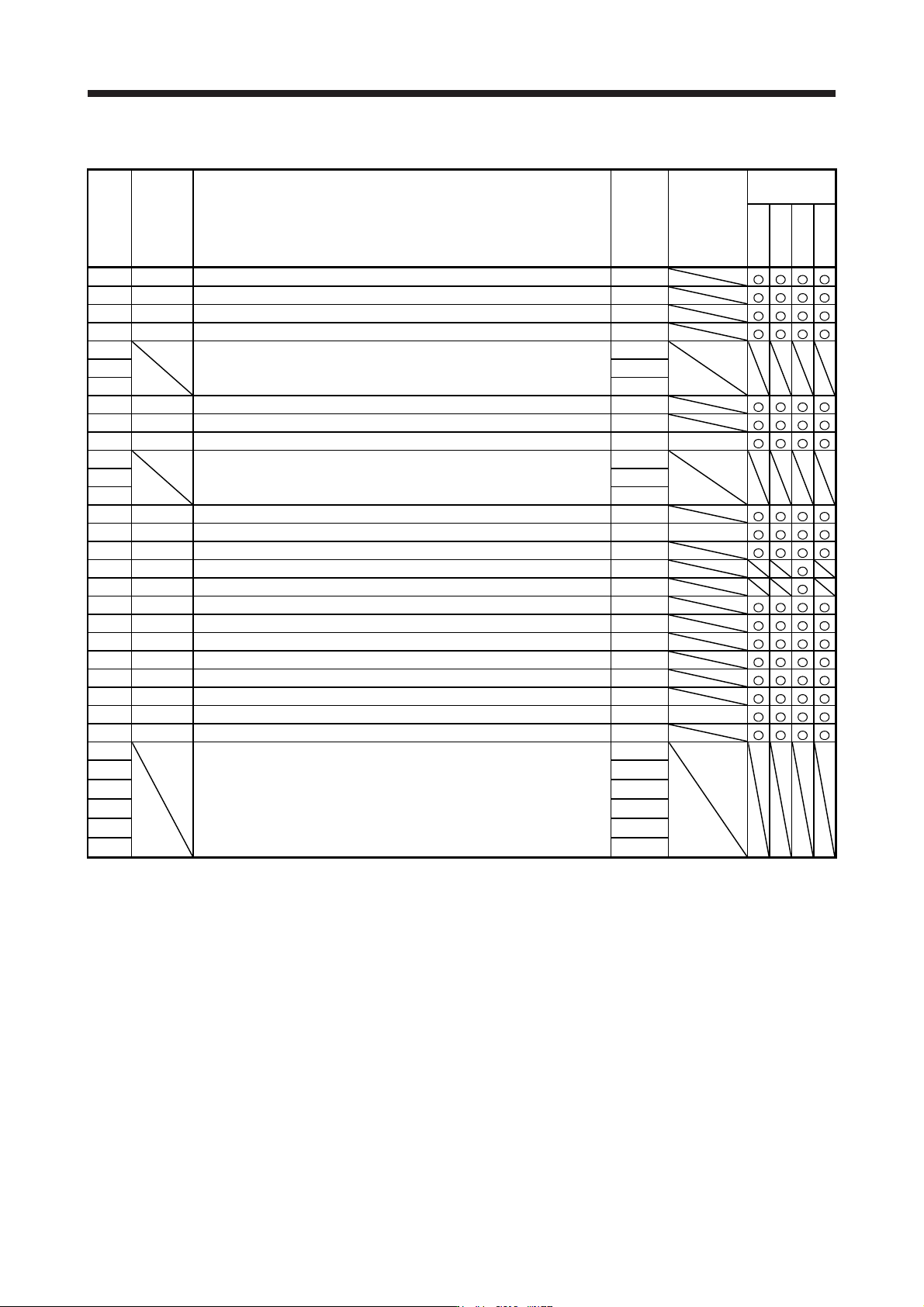
5.1.1 Basic setting parameters ([Pr. PA_ _ ])
No. Symbol Name
Initial
value
Unit
Operation
mode
Standard
Full.
Lin.
D.D.
PA01 **STY Operation mode 1000h
PA02 **REG Regenerative option 0000h
PA03 *ABS Absolute position detection system 0000h
PA04 *AOP1 Function selection A-1 2000h
PA05 For manufacturer setting 10000
PA06 1
PA07 1
PA08 ATU Auto tuning mode 0001h
PA09 RSP Auto tuning response 16
PA10 INP In-position range 1600 [pulse]
PA11 For manufacturer setting 1000.0
PA12 1000.0
PA13 0000h
PA14 *POL Rotation direction selection/travel direction selection 0
PA15 *ENR Encoder output pulses 4000 [pulse/rev]
PA16 *ENR2 Encoder output pulses 2 1
PA17 **MSR Servo motor series setting 0000h
PA18 **MTY Servo motor type setting 0000h
PA19 *BLK Parameter writing inhibit 00ABh
PA20 *TDS Tough drive setting 0000h
PA21 *AOP3 Function selection A-3 0001h
PA22 **PCS Position control composition selection 0000h
PA23 DRAT Drive recorder arbitrary alarm trigger setting 0000h
PA24 AOP4 Function selection A-4 0000h
PA25 OTHOV One-touch tuning - Overshoot permissible level 0 [%]
PA26 *AOP5 Function selection A-5 0000h
PA27 For manufacturer setting 0000h
PA28 0000h
PA29 0000h
PA30 0000h
PA31 0000h
PA32 0000h