sh030106u.pdf - 第446页
11. OPT I ONS AND PER IPH ERA L EQU IPM ENT 11 - 12 5 (3) Fuses (betwe en P/+ and P4, be tween N/- a nd N-) The followi ng tabl e shows t he recom mended fus es whi ch are to be ins talled b etween th e FR-XC-(H) a nd se…
11. OPTIONS AND PERIPHERAL EQUIPMENT
11 - 124
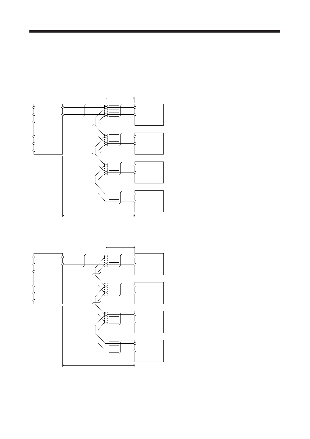
(2) Wir
e size selection example (between P/+ and P4, between N/- and N-)
When connecting multiple servo amplifiers to the FR-XC, junction terminal blocks must be used for the
wiring to terminals P4 and N- on the servo amplifiers. Connect the servo amplifiers in order with the
largest capacity first.
(a) 200 V class
R2/L12
S2/L22
T2/L32
R/L1
S/L2
T/L3
P/+
N/-
P4
N-
50 mm
2
P4
N-
P4
N-
P4
N-
22 mm
2
8 mm
2
22 mm
2
8 mm
2
5.5 mm
2
3.5 mm
2
FR-XC-55K Servo amplifier (15 kW)
First unit: Total of servo amplifier capacities
15 kW + 7 kW + 3.5 kW + 2.0 kW = 27.5 kW
50 mm
2
corresponding to 27.5 kW
Second unit: Total of servo amplifier capacities
7 kW + 3.5 kW + 2.0 kW = 12.5 kW
22 mm
2
corresponding to 15 kW
Third unit: Total of servo amplifier capacities
3.5 kW + 2.0 kW = 5.5 kW
8 mm
2
corresponding to 7 kW
Fourth unit: Total of servo amplifier capacities
2.0 kW = 2.0 kW
3.5 mm
2
corresponding to 2 kW
Servo amplifier (7 kW)
Servo amplifier (3.5 kW)
Servo amplifier (2 kW)
Total wiring length 5 m or shorter
Junction terminal
Wiring as short as possible
(b) 400
V class
R2/L12
S2/L22
T2/L32
R/L1
S/L2
T/L3
P/+
N/-
P4
N-
22 mm
2
P4
N-
P4
N-
P4
N-
8 mm
2
5.5 mm
2
8 mm
2
5.5 mm
2
3.5 mm
2
2 mm
2
FR-XC-H55K Servo amplifier (15 kW)
First unit: Total of servo amplifier capacities
15 kW + 7 kW + 3.5 kW + 2.0 kW = 27.5 kW
22 mm
2
corresponding to 27.5 kW
Second unit: Total of servo amplifier capacities
7 kW + 3.5 kW + 2.0 kW = 12.5 kW
8 mm
2
corresponding to 15 kW
Third unit: Total of servo amplifier capacities
3.5 kW + 2.0 kW = 5.5 kW
5.5 mm
2
corresponding to 7 kW
Fourth unit: Total of servo amplifier capacities
2.0 kW = 2.0 kW
2 mm
2
corresponding to 2 kW
Servo amplifier (7 kW)
Servo amplifier (3.5 kW)
Servo amplifier (2 kW)
Total wiring length 5 m or shorter
Junction terminal
Wiring as short as possible
11. OPTIONS AND PERIPHERAL EQUIPMENT
11 - 125
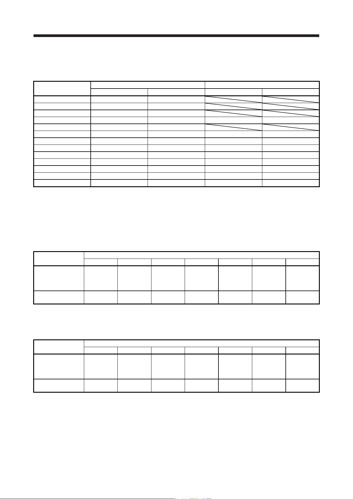
(3)
Fuses (between P/+ and P4, between N/- and N-)
The following table shows the recommended fuses which are to be installed between the FR-XC-(H) a
nd
servo amplifier.
Servo amplifier capacity
[kW]
200 V class 400 V class
Fuse rating [A] Model (Note) Fuse rating [A] Model (Note)
0.1 20 6.900CPGR10.38 0020
0.2 20 6.900CPGR10.38 0020
0.4 25 6.900CPGR10.38 0025
0.6 25 6.900CPGR10.38 0025 20 6.900CPGR10.38 0020
0.75 30 6.900CPGR10.38 0030
1 32 6.900CPGR10.38 0032 20 6.900CPGR10.38 0020
2 63 6.9URD30TTF0063 25 6.900CPGR10.38 0025
3.5 80 6.9URD30TTF0080 63 6.9URD30TTF0063
5 160 6.9URD30TTF0160 80 6.9URD30TTF0080
7 200 6.9URD30TTF0200 100 6.9URD30TTF0100
11 250 6.9URD30TTF0250 160 6.9URD30TTF0160
15 315 6.9URD30TTF0315 160 6.9URD30TTF0160
22 350 6.9URD30TTF0350 200 6.9URD30TTF0200
Note. Manufacturer: Mersen Fma Japan KK
Service inquiries: Sun-wa Technos Corp.
(4) Mol
ded-case circuit breakers/earth-leakage current breakers and magnetic contactors
Recommended molded-case circuit breakers/earth-leakage current breakers and magnetic contactors
are listed in the table below.
(a) 200 V class
Item
FR-XC-_
7.5K 11K 15K 22K 30K 37K 55K
Molded-case circuit
breaker or earth-
leakage current
breaker (Note)
100AF 60A
(30AF 30A)
100AF 75A
(50AF 50A)
225AF 125A
(100AF 75A)
225AF 175A
(100AF 100A)
225AF 225A
(125AF 125A)
400AF 250A
(125AF 125A)
400AF 400A
(225AF 175A)
Magnetic contactor
(Note)
S-T35
(S-T21)
S-T50
(S-T35)
S-T65
(S-T50)
S-T100
(S-T65)
S-N125
(S-T80)
S-N150
(S-T100)
S-N220
(S-N125)
Note. Models in parentheses can be used when the rated capacity of multifunction regeneration converter ≥ total capacity of connected
servo amplifiers × 2.
(b) 400
V class
Item
FR-XC-H_
7.5K 11K 15K 22K 30K 37K 55K
Molded-case circuit
breaker or earth-
leakage current
breaker (Note)
30AF 30A
(30AF 15A)
50AF 50A
(30AF 20A)
100AF 60A
(30AF 30A)
100AF 100A
(50AF 50A)
225AF 125A
(60AF 60A)
225AF 150A
(100AF 75A)
225AF 200A
(100AF 100A)
Magnetic contactor
(Note)
S-T21
S-T25
(S-T21)
S-T35
(S-T21)
S-T50
(S-T25)
S-T65
(S-T35)
S-T80
(S-T50)
S-N125
(S-T65)
Note. Models in parentheses can be used when the rated capacity of multifunction regeneration converter ≥ total capacity of connected
servo amplifiers × 2.

11. OPTIONS AND PERIPHERAL EQUIPMENT
11 - 126
MEMO