sh030106u.pdf - 第673页
APPENDIX App. - 42 App. 11. 3.3 Sp ecific ations (1) Speci al co ating Using the MR-J4 s eries in a n atmospher e cont ainin g a cor rosive gas may caus e its c orrosion with time , resulting in a malfu nction. F or the …
APPENDIX
App. - 41
App. 11.3 Special coating-specification product (IEC 60721-3-3:1994 Class 3C2)
App. 11.3.1 Summary
This section explains servo amplifiers with a special coating specification. Items not given in this section will
be the same as MR-J4-_B_(-RJ).
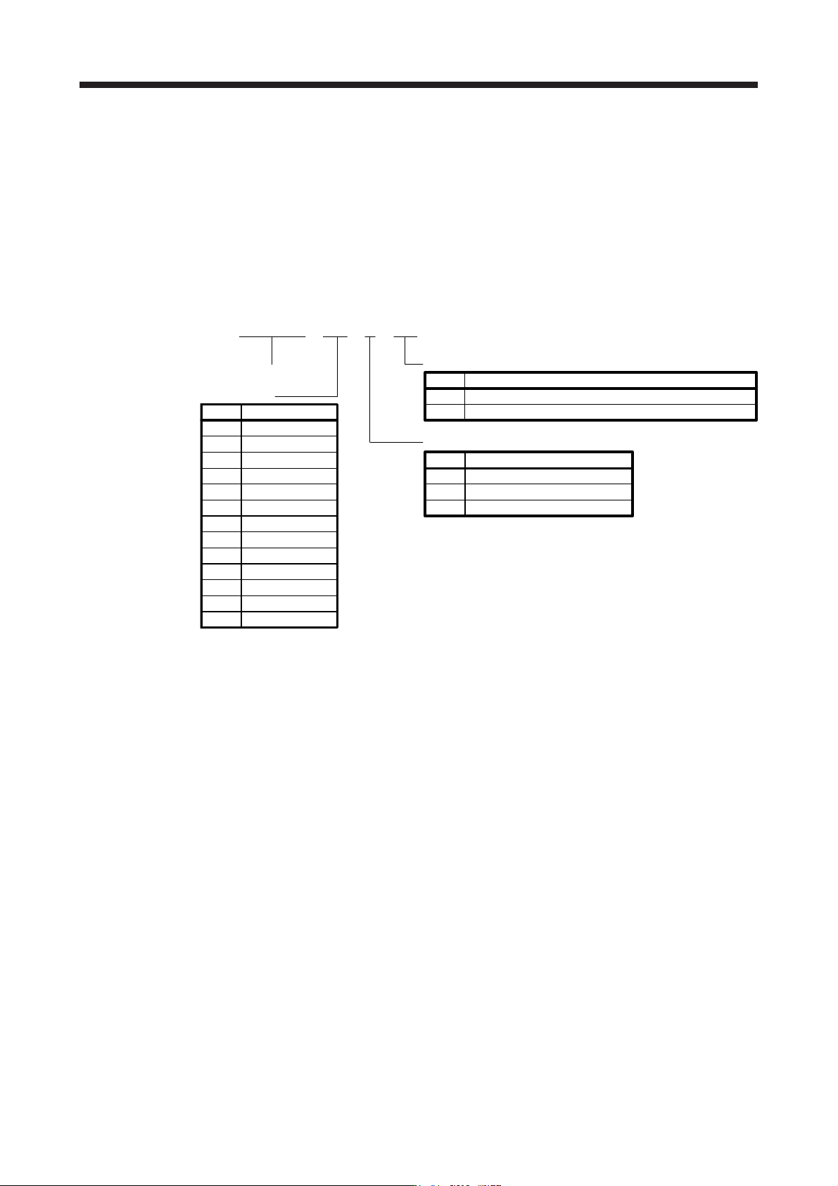
App. 11.3.2 Model
The following describes what each block of a model name indicates. Not all combinations of the symbols are
available.
Series
Rated output
Symbol Rated output [kW]
10 0.1
20 0.2
40 0.4
60 0.6
70 0.75
100 1
200
2
350 3.5
500 5
700 7
11K 11
15K 15
22K 22
Power supply
Symbol Power supply
None
3-phase 200 V AC to 240 V AC
4 3-phase 380 V AC to 480 V AC
Special specifications
Symbol Special specifications
KS MR-J4-_B_-RJ with a special coating specification (3C2)
EB MR-J4-_B_ with a special coating specification (3C2)
1 1-phase 100 V AC to 120 V AC
MR J BBE446---0
APPENDIX
App. - 42
App. 11.3.3 Specifications
(1) Special coating
Using the MR-J4 series in an atmosphere containing a corrosive gas may cause its corrosion with time,
resulting in a malfunction. For the printed circuit board of the servo amplifiers with a special coating
specification, a urethane coating agent is applied to some parts capable of being coated technically
(except LEDs, connectors, terminal blocks, etc.) to improve the resistance to corrosive gases. Use a
servo amplifier with a special coating specification specifically for applications susceptible to corrosive
gases, including tire manufacturing and water treatment. Although the special coating-specification
products have the improved resistance to corrosive gases, proper operations in environments mentioned
above are not guaranteed. Therefore, perform periodic inspections for any abnormality.
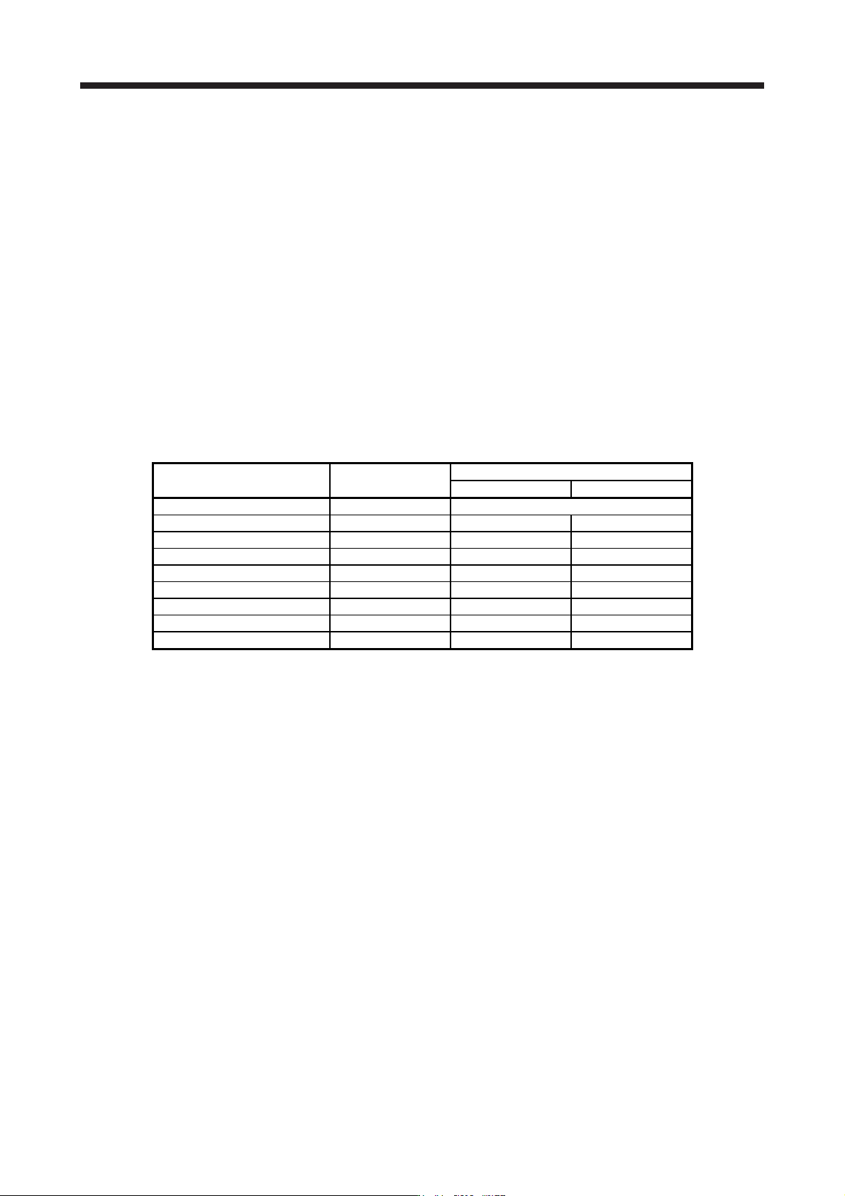
(2) Standard for corrosive gases
In IEC 60721-3-3, corrosive gases refer to sea salt, sulfur dioxide, hydrogen sulfide, chlorine, hydrogen
chloride, hydrogen fluoride, ammonia, ozone, and nitrogen oxides shown in the environmental parameter
column of the table below.
The table also shows the corrosive gas concentrations defined in IEC 60721-3-3:1994 Class 3C2.
Environmental parameter Unit
3C2
Mean value Maximum value
a) Sea salt None Salt mist
b) Sulfur dioxide cm
3
/m
3
0.11 0.37
c) Hydrogen sulfide cm
3
/m
3
0.071 0.36
d) Chlorine cm
3
/m
3
0.034 0.1
e) Hydrogen chloride cm
3
/m
3
0.066 0.33
f) Hydrogen fluoride cm
3
/m
3
0.012 0.036
g) Ammonia cm
3
/m
3
1.4 4.2
h) Ozone cm
3
/m
3
0.025 0.05
i) Nitrogen oxides cm
3
/m
3
0.26 0.52
The special coating-specification products have the improved corrosion resistance in environments with
corrosive gas concentrations conforming to IEC 60721-3-3:1994 Class 3C2. We tested typical models
and confirmed that their corrosive gas resistance was improved, compared with the standard models.
APPENDIX
App. - 43
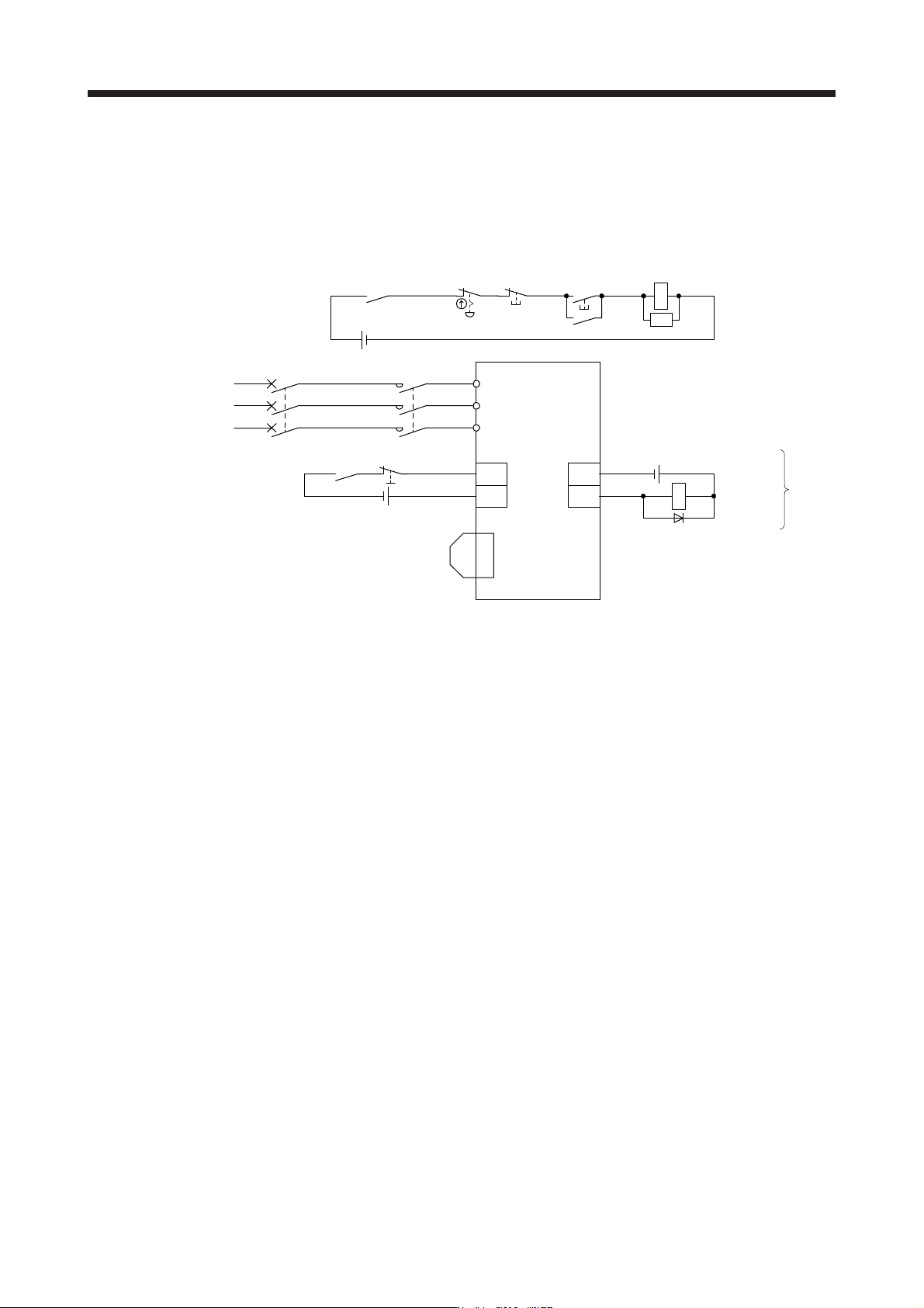
App. 12 Driving on/off of main circuit power supply with DC power supply
App. 12.1 Connection example
The power circuit is common to all capacity type of servo amplifiers. For the signal and wirings not given in
this section, refer to section 3.1.1 to 3.1.3.
MC (Note 3)
ALM
DOCOM
CN3
(Note 2)
24 V DC (Note 6)
24 V DC (Note 6)
24 V DC (Note 7,8)
Malfunction
(Note 9)
RA1
L1
L2
L3
Power supply
(Note 1)
Servo amplifier
Malfunction
RA1
OFF
MC
ON
MC
Emergency stop switch
CN3
(Note 2)
Forced stop 2
EM2
CN8
(Note 5)
Short-circuit connector
(Packed with the servo amplifier)
(Note 4)
Main circuit
power supply
MCCB
SK
DOCOM
Note 1. For the power suppl
y
specifications, refer to section 1.3.
2. This dia
g
ram shows sink I/O interface. For source I/O interface, refer to section 3.9.3.
3. Use the magnetic contactor with an operation delay time (interval between current being applied to the coil until closure of
contacts) of 80 ms or less (160 ms or less for 5 kW or more). Depending on the main circuit voltage and operation pattern, bus
voltage decreases, and that may cause the forced stop deceleration to shift to the dynamic brake deceleration. When dynamic
brake deceleration is not required, slow the time to turn off the ma
g
netic contactor.
4. Configure a circuit to turn off EM2 when the main circuit power is turned off to prevent an unexpected restart of the servo
amplifier.
5. When not usin
g
the STO function, attach the short-circuit connector came with a servo amplifier.
6. The illustration of the 24 V DC power supply is divided between input signal and output signal for convenience. However, they
can be confi
g
ured b
y
one.
7. Drivin
g
the on switch and off switch with the DC power suppl
y
meets IEC/EN 60204-1 requirements.
8. Do not use the 24 V DC interface power supply for the magnetic contactor DC power supply. Always use the power supply
desi
g
ned exclusivel
y
for the ma
g
netic contactor.
9. If ALM (Malfunction) output is disabled with the parameter, configure the power supply circuit which switches off the magnetic
contactor after detection of alarm occurrence on the controller side.