sh030106u.pdf - 第132页
4. STA RTUP 4 - 7 (2) Parameter setting POINT The foll owing enc oder ca bles are of four-w ire ty pe. When using any o f these encoder ca bles, se t [Pr. PC 04] to " 1 _ _ _" to selec t the four -wire type. In…

4. STARTUP
4 - 6
(b) 24 V DC or higher voltage is not applied to the pins of the CN3 connector.
(c) Plate and DOCOM of the CN3 connector is not shorted.
Servo amplifier
DOCOM
Plate
CN3
4.1.3 Surrounding environment
(1) Cable routing
(a) The wiring cables should not be stressed.
(b) The encoder cable should not be used in excess of its bending life. (Refer to section 10.4.)
(c) The connector of the servo motor should not be stressed.
(2) Environment
Signal cables and power cables are not shorted by wire offcuts, metallic dust or the like.
4.2 Startup
Connect the servo motor with a machine after confirming that the servo motor operates properly alone.
(1) Power on
When the main and control circuit power supplies are turned on, "b01" (for the first axis) appears on the
servo amplifier display.
When the absolute position detection system is used in a rotary servo motor, first power-on results in
[AL. 25 Absolute position erased] and the servo-on cannot be ready. The alarm can be deactivated by
then switching power off once and on again.
Also, if power is switched on at the servo motor speed of 3000 r/min or higher, position mismatch may
occur due to external force or the like. Power must therefore be switched on when the servo motor is at
a stop.
4. STARTUP
4 - 7
(2) Parameter setting
POINT
The following encoder cables are of four-wire type. When using any of these
encoder cables, set [Pr. PC04] to "1 _ _ _" to select the four-wire type. Incorrect
setting will result in [AL. 16 Encoder initial communication error 1].
MR-EKCBL30M-L
MR-EKCBL30M-H
MR-EKCBL40M-H
MR-EKCBL50M-H
If using the MR-J4-_B-RJ servo amplifier with the DC power supply input, set
[Pr. PC20] to "_ _ _1".
Set the parameters according to the structure and specifications of the machine. Refer to chapter 5 for
details.
After setting the above parameters, turn power off as necessary. Then switch power on again to enable
the parameter values.
(3) Servo-on
Enable the servo-on with the following procedure.
(a) Switch on main circuit power supply and control circuit power supply.
(b) Transmit the servo-on command with the servo system controller.
When the servo-on status is enabled, the servo amplifier is ready to operate and the servo motor is
locked.
(4) Home position return
Always perform home position return before starting positioning operation.
(5) Stop
Turn off the servo-on command after the servo motor has stopped, and then switch the power off.
If any of the following situations occurs, the servo amplifier suspends the running of the servo motor and
brings it to a stop.
Refer to section 3.10 for the servo motor with an electromagnetic brake.
Operation/command Stopping condition
Servo system
controller
Servo-off command The base circuit is shut off and the servo motor coasts.
Ready-off command
The base circuit is shut off and the dynamic brake operates to
bring the servo motor to a stop.
Forced stop command
The servo motor decelerates to a stop with the command. [AL.
E7 Controller forced stop warning] occurs.
Servo amplifier
Alarm occurrence
The servo motor decelerates to a stop with the command. With
some alarms, however, the dynamic brake operates to bring the
servo motor to a stop. (Refer to section 8. (Note))
EM2 (Forced stop 2) off
The servo motor decelerates to a stop with the command. [AL.
E6 Servo forced stop warning] occurs. EM2 has the same
function as EM1 in the torque control mode. Refer to section 3.5
for EM1.
STO (STO1, STO2) off
The base circuit is shut off and the dynamic brake operates to
bring the servo motor to a stop.
Note. Only a list of alarms and warnings is listed in chapter 8. Refer to "MELSERVO-J4 Servo Amplifier
Instruction Manual
(
Troubleshootin
g)
" for details of alarms and warnin
g
s.
4. STARTUP
4 - 8
4.3 Switch setting and display of the servo amplifier
Switching to the test operation mode, deactivating control axes, and setting control axis No. are enabled with
switches on the servo amplifier.
On the servo amplifier display (three-digit, seven-segment LED), check the status of communication with the
servo system controller at power-on, and the axis number, and diagnose a malfunction at occurrence of an
alarm.
4.3.1 Switches
WARNING
When switching the axis selection rotary switch (SW1) and auxiliary axis number
setting switch (SW2), use insulated screw driver. Do not use a metal screw driver.
Touching patterns on electronic boards, lead of electronic parts, etc. may cause
an electric shock.
POINT
Turning "ON (up)" all the control axis setting switches (SW2) enables an
operation mode for manufacturer setting and displays "off". The mode is not
available. Set the control axis setting switches (SW2) correctly according to this
section.
Cycling the main circuit power supply and control circuit power supply enables
the setting of each switch.
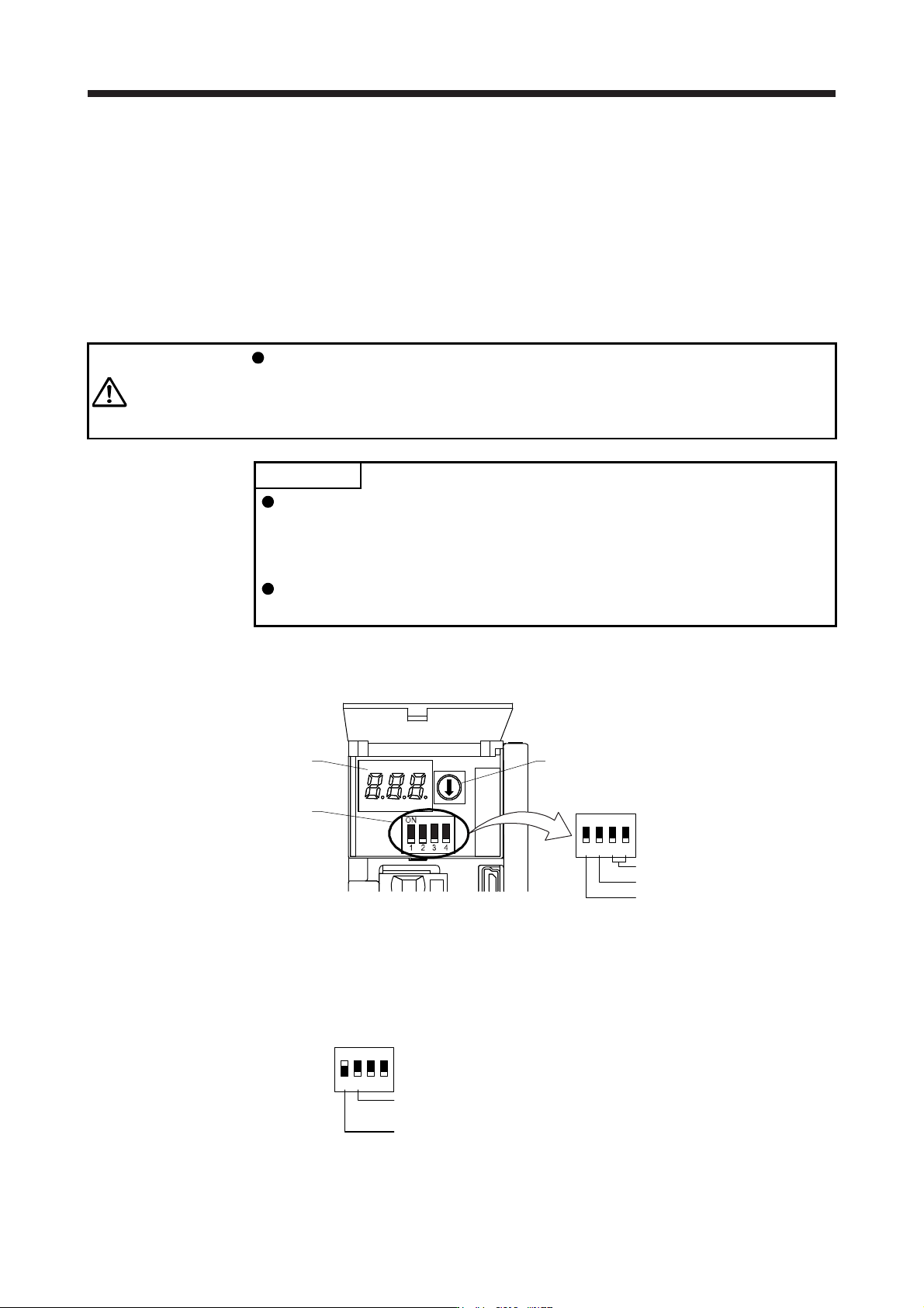
The following explains the test operation select switch, the disabling control axis switch, auxiliary axis
number setting switches, and the axis selection rotary switch.
3-digit, 7-segment LED
Control axis setting switch
(SW2)
Axis selection rotary switch
(SW1)
Auxiliary axis number setting switch
Disabling control axis switch
Test operation select switch
1
ON
2 3 4
(1) Test operation select switch (SW2-1)
To use the test operation mode, turn "ON (up)" the switch. Turning "ON (up)" the switch enables the test
operation mode. In the test operation mode, the functions such as JOG operation, positioning operation,
and machine analyzer are available with MR Configurator2. Before turning "ON (up)" the test operation
select switch, turn "OFF (down)" the disabling control axis switch.
Disabling control axis switch
Set to the "OFF (down)" position.
Test operation select switch
Set to the "ON (up)" position.
1
ON
2 3 4