sh030106u.pdf - 第536页
16. FULLY CLOSE D L OOP SYS TEM 16 - 11 (2) Selecti on of f ully cl osed lo op system By setting [ Pr. PA01], [ Pr. PE 01] and the contr ol com mand of co ntroller, t he co ntrol m ethod c an be selected as show n in th …
16. FULLY CLOSED LOOP SYSTEM
16 - 10
16.3 Operation and functions
16.3.1 Startup
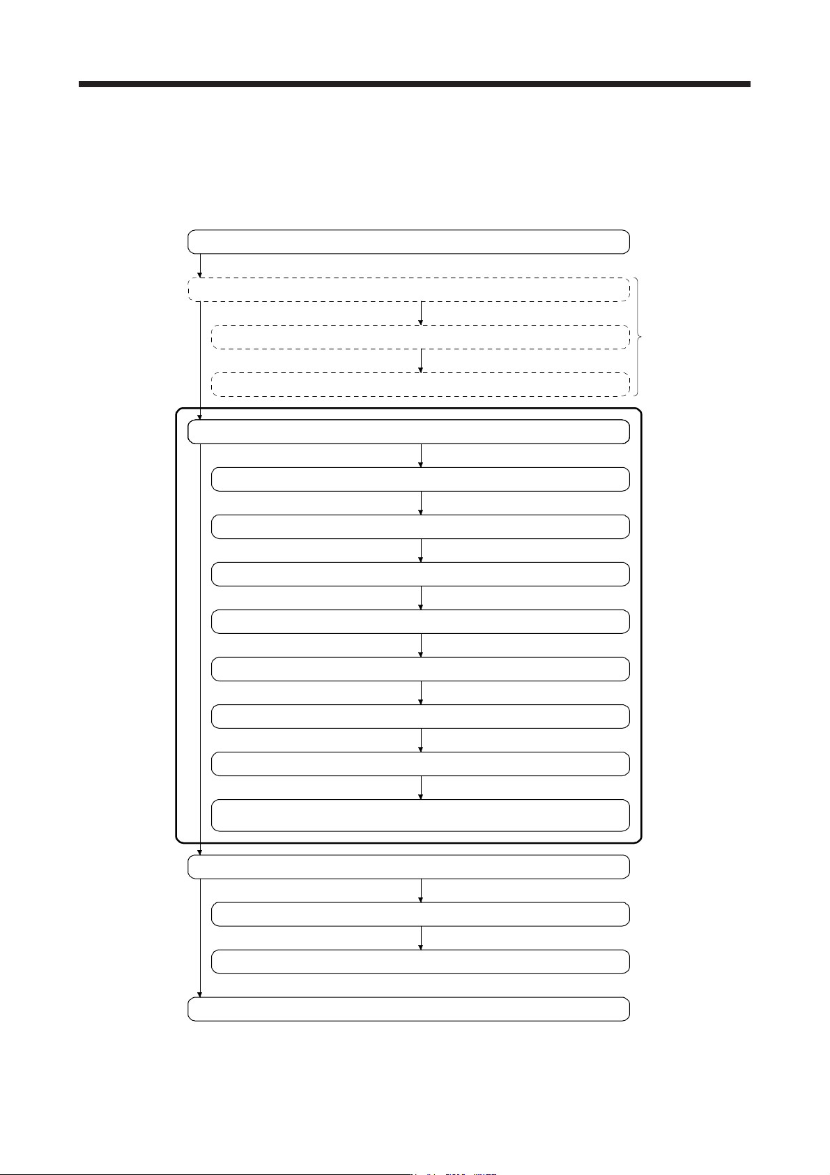
(1) Startup procedure
Start up the fully closed loop system in the following procedure.
Positioning operation check using the controller (Refer to section 16.3.3.)
Positioning operation check using MR Configurator2
Gain adjustment
Completion of installation and wiring
Positioning operation check using MR Configurator2
Adjustment and operation check in semi closed loop system
Gain adjustment
Adjustment and operation check in fully closed loop system
Selection of fully closed loop system (Refer to (2) in this section.)
Selection of load-side encoder communication system (Refer to (3) in this section.)
Adjustment of dual feedback switching filter.
(for dual feedback control) (Refer to (5) in this section.)
Setting of load-side encoder polarity (Refer to (4) in this section.)
Home position return operation (Refer to section 16.3.2.)
Positioning operation
Completion of fully closed loop system startup
Check that the servo
equipment is normal.
Do as necessary.
Setting of load-side encoder electronic gear (Refer to (5) in this section.)
Confirmation of load-side encoder position data (Refer to (6) in this section.)
16. FULLY CLOSED LOOP SYSTEM
16 - 11
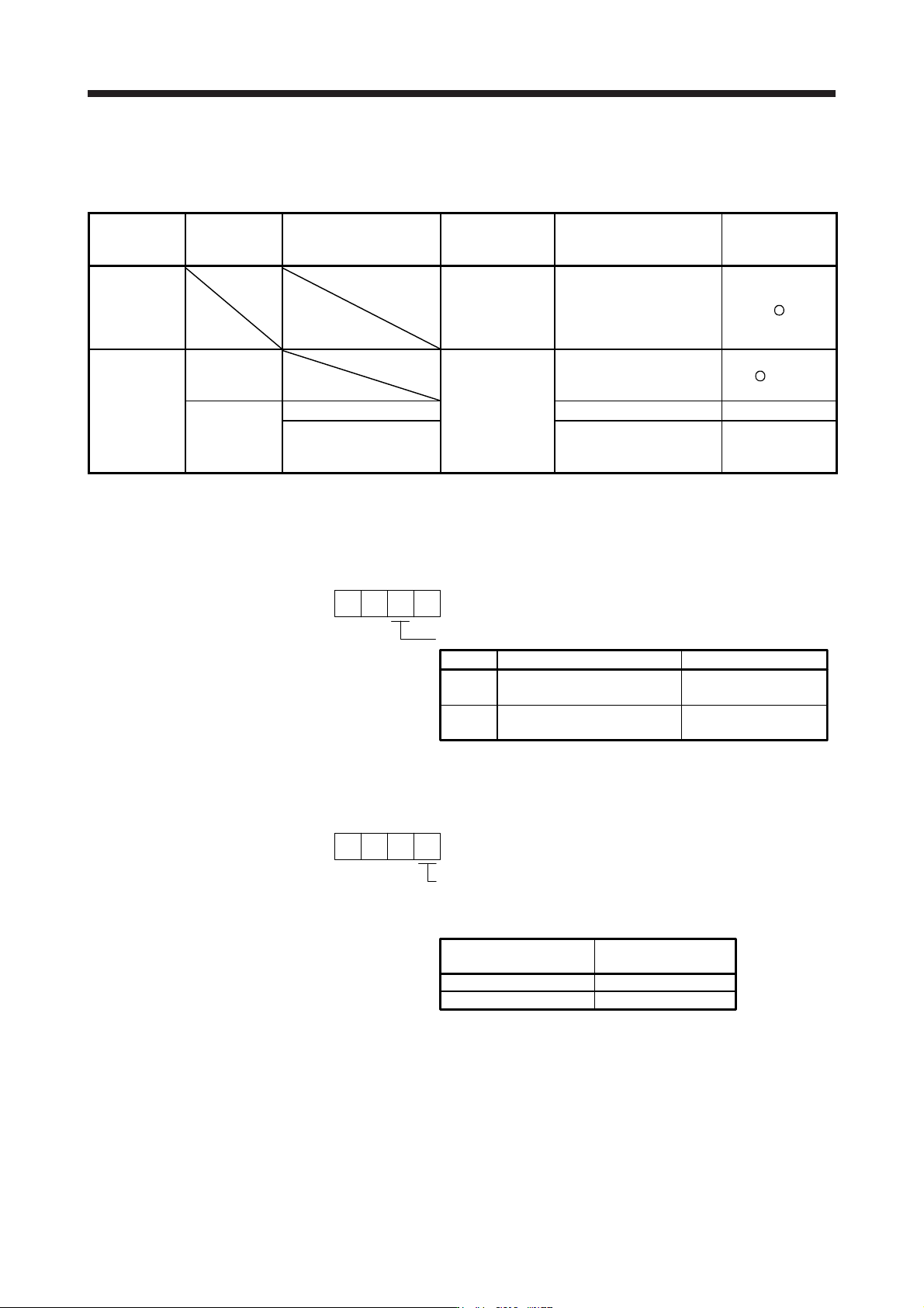
(2) Selection of fully closed loop system
By setting [Pr. PA01], [Pr. PE01] and the control command of controller, the control method can be
selected as shown in the following table.
[Pr. PA01] [Pr. PE01]
Semi closed loop control/
fully closed loop control
switching signal
Command unit Control System
Absolute position
detection
system
"_ _ 0 _"
Semi closed
loop system
(standard
control mode)
Servo motor
encoder unit
Semi closed loop control
"_ _ 1 _ "
Fully closed
loop system
(fully closed
loop control
mode)
"_ _ _ 0"
Load-side encoder
unit
Dual feedback
control (fully closed loop
control)
(Note)
"_ _ _ 1" Off
Semi closed loop control
×
On
Dual feedback
control (fully closed loop
control)
×
Note.
A
pplicable when the load-side encoder is set as the absolute position encoder.
(a) Operation mode selection
Select a operation mode.
Operation mode selection
[Pr. PA01]
10 0
Semi closed loop system
(Standard control mode)
Fully closed loop system
(Fully closed loop control mode)
Load-side encoder
resolution unit
Set value
0
1
Operation mode
Servo motor-side
resolution unit
Control unit
(b) Semi closed loop control/fully closed loop control selection
Select the semi closed loop control/fully closed loop control.
Fully closed loop control selection
0: Always enabled
1: Switching using the control command of controller
(switching between semi closed/fully closed)
00
Selection using the control
command of controller
OFF
ON
Semi closed loop control
Fully closed loop control
Control method
When the operation mode selection in [Pr. PA01] is set to "_ _ 1 _"
(fully closed loop system), this setting is enabled.
0
[Pr. PE01]
16. FULLY CLOSED LOOP SYSTEM
16 - 12
(3) Selection of load-side encoder communication method
The communication method changes depending on the load-side encoder type. Refer to table 1.1 and
"Linear Encoder Instruction Manual" for the communication method for each load-side encoder.
Select the cable to be connected to CN2L connector in [Pr. PC26].
000
[Pr. PC26]
Load-side encoder cable communication method selection
0: Two-wire type
1: Four-wire type
When using a load-side encoder of A/B/Z-phase differential output method, set "0".
Incorrect setting will trigger [AL. 70] and [AL. 71]. Setting "1" while
using a servo amplifier other than MR-J4-_B_-RJ will trigger [AL. 37].
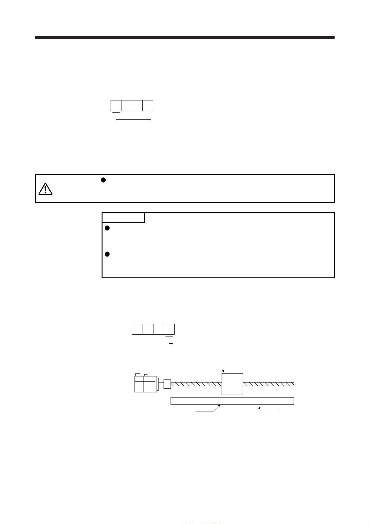
(4) Setting of load-side encoder polarity
CAUTION
Do not set an incorrect direction to "Encoder pulse count polarity selection" in [Pr.
PC27]. An abnormal operation and a machine collision may occur if an incorrect
direction is set, which cause a fault and parts damaged.
POINT
"Encoder pulse count polarity selection" in [Pr. PC27] is not related to [Pr. PA14
Rotation direction selection]. Make sure to set the parameter according to the
relationships between servo motor and linear encoder/rotary encoder.
Do not set an incorrect direction to "Encoder pulse count polarity selection" in
[Pr. PC27]. Doing so may cause [AL. 42 Fully closed loop control error] during
the positioning operation.
(a) Parameter setting method
Set the load-side encoder polarity to be connected to CN2L connector in order to match the CCW
direction of servo motor and the increasing direction of load-side encoder feedback.
000
[Pr. PC27]
Encoder pulse count polarity selection
0: Load-side encoder pulse increasing direction in the servo motor CCW
1: Load-side encoder pulse decreasing direction in the servo motor CC
W
Servo motor
Linear encoder
Servo motor CCW direction
Address increasing direction of linear encoder
(b) How to confirm the load-side encoder feedback direction
For the way of confirming the load-side encoder feedback direction, refer to (6) in this section.