sh030106u.pdf - 第124页
3. SIG NALS A ND WIRI NG 3 - 47 (2) When you do not use the fo rced s top deceler ation f unc tion POINT To disable the func tion, s et " 0 _ _ _" in [ Pr. PA 04]. (a) Servo-on command (from controller) on/off …
3. SIGNALS AND WIRING
3 - 46
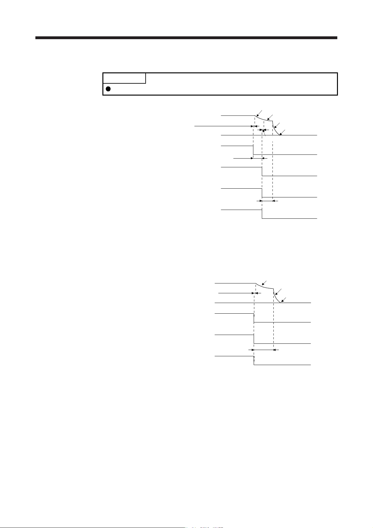
(e) Main circuit power supply off during control circuit power supply on
POINT
In the torque control mode, the forced stop deceleration function is not available.
ON
OFF
ON
OFF
(Note 2)
The time until a voltage
drop is detected.
ON
OFF
Dynamic brake
Forced stop deceleration
Dynamic brake
+ Electromagnetic brake
Electromagnetic brake
Operation delay time of
the electromagnetic brake
0 r/min
Approx. 10 ms
(Note 1)
Servo motor speed
Main circuit
power supply
Base circuit
(Energy supply to
the servo motor)
MBR
(Electromagnetic
brake interlock)
A
LM (Malfunction)
ON (no alarm)
OFF (alarm)
Note 1. ON: Electromagnetic brake is not activated.
OFF: Electroma
g
netic brake is activated.
2. Variable accordin
g
to the operation status.
(f) Ready-off command from controller
Electromagnetic brake
MBR
(Electromagnetic
brake interlock)
Base circuit
Servo motor speed
Ready-on command
(from controller)
(Note)
ON
OFF
ON
OFF
ON
OFF
Approx. 10 ms
0 r/min
Dynamic brake
Dynamic brake
+ Electromagnetic brake
Operation delay time of
the electromagnetic brake
Note. ON: Electromagnetic brake is not activated.
OFF: Electroma
g
netic brake is activated.
3. SIGNALS AND WIRING
3 - 47
(2) When you do not use the forced stop deceleration function
POINT
To disable the function, set "0 _ _ _" in [Pr. PA04].
(a) Servo-on command (from controller) on/off
It is the same as (1) (a) in this section.
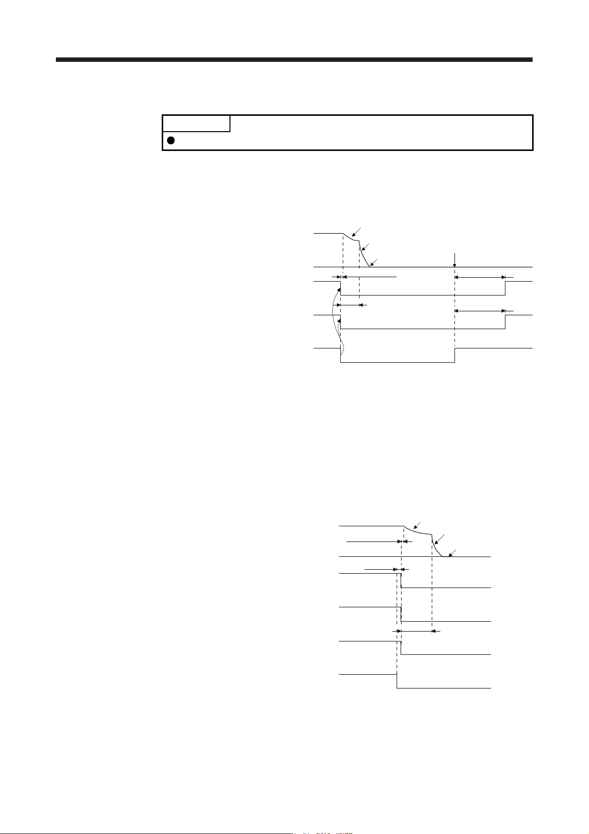
(b) Off/on of the forced stop command (from controller) or EM1 (Forced stop 1)
Dynamic brake
Dynamic brake
+ Electromagnetic brake
Electromagnetic brake
MBR
(Electromagnetic
brake interlock)
Operation delay time
of the electromagnetic
brake
Approx. 210 ms
Approx. 210 ms
Electromagnetic brake
has released.
(Note)
ON
OFF
Base circuit
ON
OFF
Servo motor speed
Forced stop command
(from controller)
or
EM1 (Forced stop 1)
ON (Disabled)
OFF (Enabled)
0 r/min
Approx. 10 ms
Note. ON: Electromagnetic brake is not activated.
OFF: Electroma
g
netic brake is activated.
(c) Alarm occurrence
The operation status during an alarm is the same as section 3.7.2.
(d) Both main and control circuit power supplies off
It is the same as (1) (d) in this section.
(e) Main circuit power supply off during control circuit power supply on
Dynamic brake
Dynamic brake
+ Electromagnetic brake
Electromagnetic brake
Operation delay time of
the electromagnetic brake
MBR
(Electromagnetic
brake interlock)
(Note 2)
Base circuit
Alarm
[AL. 10 Undervoltage]
No alarm
Alarm
Servo motor speed
Approx. 10 ms
(Note 1)
ON
OFF
ON
OFF
Main circuit
power supply
ON
OFF
0 r/min
Note 1. Variable accordin
g
to the operation status.
2. ON: Electromagnetic brake is not activated.
OFF: Electroma
g
netic brake is activated.
3. SIGNALS AND WIRING
3 - 48
(f) Ready-off command from controller
It is the same as (1) (f) in this section.
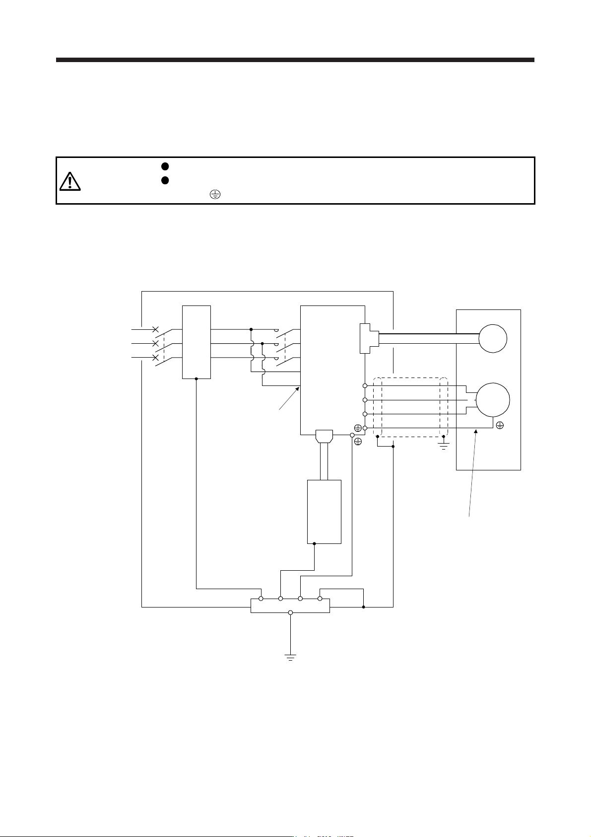
3.11 Grounding
WARNING
Ground the servo amplifier and servo motor securely.
To prevent an electric shock, always connect the protective earth (PE) terminal
(marked
) of the servo amplifier to the protective earth (PE) of the cabinet.
The servo amplifier switches the power transistor on-off to supply power to the servo motor. Depending on
the wiring and ground cable routing, the servo amplifier may be affected by the switching noise (due to di/dt
and dv/dt) of the transistor. To prevent such a fault, refer to the following diagram and always ground.
To conform to the EMC Directive, refer to "EMC Installation Guidelines".
Ensure to connect the wire to the
PE terminal of the servo amplifier.
Do not connect the wire directly to
the grounding of the cabinet.
(Note)
Power
supply
V
U
Cabinet
Servo motor
M
U
V
W
W
Encoder
CN2
Servo amplifier
L11
L1
L2
L3
L21
CN1A
Protective earth (PE)
Outer
box
MC
MCCB
EMC filter
Servo system
controller
Do not ground
L11 and L21.
Note. For the power suppl
y
specifications, refer to section 1.3.