sh030106u.pdf - 第562页
17. APPLICATIO N OF FUNCTIONS 17 - 11 (2) How to selec t "J3 c ompat ibility mode" using the ap plica tion " MR-J4(W) -B mod e selection" or "M R Mode Change" The appl ication "MR- J4( …
17. APPLICATION OF FUNCTIONS
17 - 10
(b) Operation when using a servo amplifier after change of specifications
For the controllers in which "Not required" is described to controller reset in table 17.3, the mode will
be switched to "J3 compatibility mode" for all axes at the first connection. It takes about 10 s for
completing the connection not depending on the number of axes.
For the controllers in which "Reset required" is described in table 17.3, the operation at the first
connection is shown in table 17.4. The servo amplifier's mode will be "J3 compatibility mode" and the
LED displays will be "rST" for all axes at the first connection to the controller as shown in table 17.4.
At the status, resetting controller once will change the display to "b##" (## means axis No.) for all
axes and all axes will be ready to connect.
(One controller reset enables to all-axis connection.)
Table 17.3 Controller reset required/not required list (after change of specifications)
Controller Model
Controller reset required/not required
Single-axis
connection
Multi-axis connection
Motion controller
R_MTCPU Not required Not required
Q17_DSCPU Not required Not required
Q17_DCPU Not required Not required
Q17_HCPU Not required Not required
Q170MCPU Not required Not required
Simple motion module
Positioning module
RD77MS_ Not required Not required
QD77MS_ Not required Not required
LD77MS_ Not required Not required
QD75MH_ Not required Not required
QD74MH_ Reset required Reset required
LD77MH_ Not required Not required
FX3U-20SSC-H Reset required Reset required
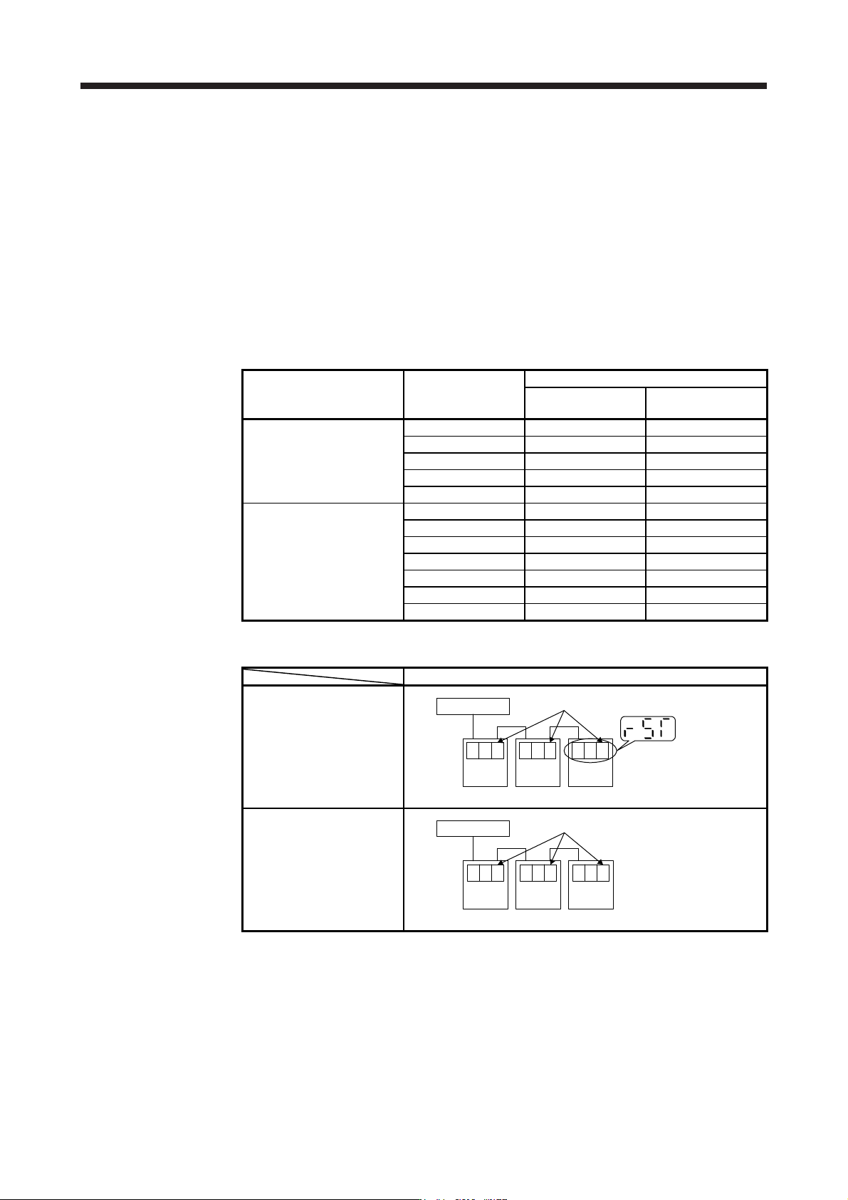
Table 17.4 Controller connection operation after change of specifications
After change of specifications (software version A5 or later)
First connection of controller
Controller
Axis
No. 1
STr
Axis
No. 2
STr
Axis
No. 3
STr
"rST" is displayed only for the first connection.
After controller reset
Controller
Axis
No. 1
01b
Axis
No. 2
02b
Axis
No. 3
03b
All axes are connected by one reset.
(c) Using servo amplifiers before and after change of specifications simultaneously
When using servo amplifiers before change of specifications and after change of specifications
simultaneously, controller reset is necessary for number of connecting axes of servo amplifiers.

17. APPLICATION OF FUNCTIONS
17 - 11
(2) How to select "J3 compatibility mode" using the application "MR-J4(W)-B mode selection" or "MR Mode
Change"
The application "MR-J4(W)-B mode selection" or "MR Mode Change" included in MR Configurator2 can
be used to manually switch the servo amplifier mode to "J3 compatibility mode" beforehand. Use it for a
solution when it is difficult to reset many times with your "Reset required" controller such as "QD74MH_".
The application "MR-J4(W)-B mode selection" and "MR Mode Change" are also available by
downloading the free trial version of MR Configurator2 from the "Mitsubishi Electric FA site". The
application "MR-J4(W)-B mode selection" and "MR Mode Change" do not have an expiration date.
Select "Change the mode".
Select "J3 compatibility mode".
Select "Operation Mode" .
17.1.9 J3 extension function
POINT
The J3 extension function is used with servo amplifiers with software version B0
or later.
To enable the J3 extension function, MR Configurator2 with software version
1.25B or later is necessary.
The J3 extension function of the amplifier differs from MR-J3-B in motion.
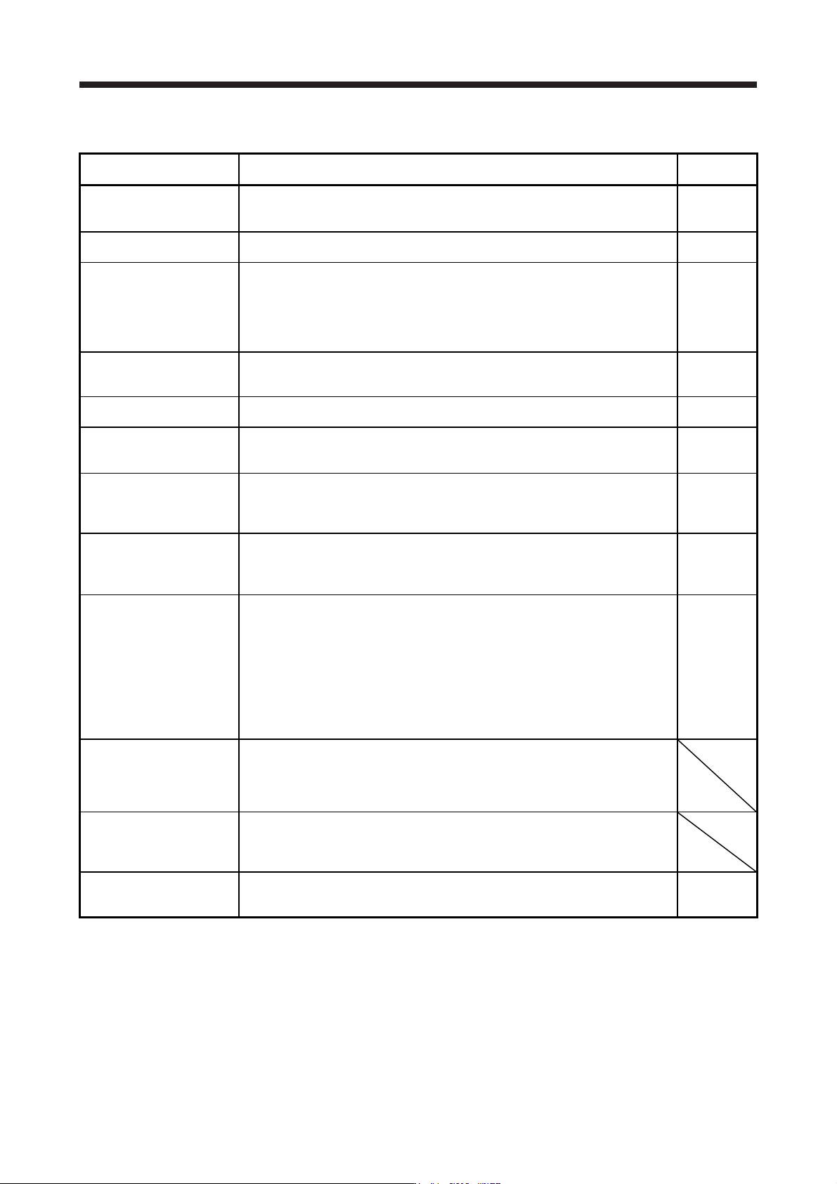
The J3 extension function is for using functions of J4 mode with J3 compatibility mode.
By enabling the J3 extension function, control response will be equal to MR-J4 series using a controller
compatible with SSCNET III.
J4 mode
J3 compatibility mode
J3 extension function enabled:
[Pr. PX01] = "_ _ _ 1"
J3 extension function disabled:
[Pr. PX01] = "_ _ _ 0"
SSCNET III/H
communication
MR-J4-B function
SSCNET III communication
The same parameter ordering as MR-
J3-B
MR-J4-B control function
Parameter added
SSCNET III communication
The same parameter ordering as MR-
J3-B
17. APPLICATION OF FUNCTIONS
17 - 12
The following shows functions used with the J3 extension function.
Function Description
Detailed
explanation
Gain switching function
(Vibration suppression control
2 and model loop gain)
You can switch gains during rotation/stop, and can use input devices to switch gains
during operation.
Section
17.1.9 (6)
Advanced vibration
suppression control II
This function suppresses vibration at the arm end or residual vibration.
Section
17.1.9 (5) (c)
Machine resonance
suppression filter 3
Machine resonance
suppression filter 4
Machine resonance
suppression filter 5
This is a filter function (notch filter) which decreases the gain of the specific frequency
to suppress the resonance of the mechanical system.
Section
17.1.9 (5) (a)
Shaft resonance suppression
filter
When a load is mounted to the servo motor shaft, resonance by shaft torsion during
driving may generate a mechanical vibration at high frequency. The shaft resonance
suppression filter suppresses the vibration.
Section
17.1.9 (5) (b)
Robust filter
This function provides better disturbance response in case low response level that
load to motor inertia ratio is high for such as roll send axes.
[Pr. PX31]
One-touch tuning
Gain adjustment is performed just by one click on a certain button on MR
Configurator2.
MR Configurator2 is necessary for this function.
Section
17.1.9 (4)
Tough drive function
This function makes the equipment continue operating even under the condition that
an alarm occurs.
The tough drive function includes two types: the vibration tough drive and the
instantaneous power failure tough drive.
Section
17.1.9 (7)
SEMI-F47 function (Note)
Enables to avoid triggering [AL. 10 Undervoltage] using the electrical energy charged
in the capacitor in case that an instantaneous power failure occurs during operation.
Use a 3-phase for the input power supply of the servo amplifier. Using a 1-phase 200
V AC for the input power supply will not comply with SEMI-F47 standard.
[Pr. PX25]
[Pr. PX28]
Section
17.1.9 (8)
Drive recorder function
This function continuously monitors the servo status and records the status transition
before and after an alarm for a fixed period of time. You can check the recorded data
on the drive recorder window on MR Configurator2 by clicking the "Graph" button.
However, the drive recorder will not operate on the following conditions.
1. You are using the graph function of MR Configurator2.
2. You are using the machine analyzer function.
3. [Pr. PX30] is set to "-1".
4. The controller is not connected (except the test operation mode).
5. An alarm related to the controller is occurrin
g
.
[Pr. PX29]
Power monitoring function
This function calculates the power running energy and the regenerative power from
the data in the servo amplifier such as speed and current. Power consumption and
others are displayed on MR Configurator2 in the system of SSCNET III/H. Since the
servo amplifier sends data to a servo system controller, you can analyze the data and
display the data on a display.
Machine diagnosis function
From the data in the servo amplifier, this function estimates the friction and vibrational
component of the drive system in the equipment and recognizes an error in the
machine parts, including a ball screw and bearing.
MR Configurator2 is necessary for this function.
Lost motion compensation
function
This function improves the response delay occurred when the machine moving
direction is reversed. This is used with servo amplifiers with software version B4 or
later.
Section
17.1.9 (9)
Note. For servo s
y
stem controllers which are available with this, contact
y
our local sales office.