sh030106u.pdf - 第42页
1. FUNCTI ONS AND CONF IGURATION 1 - 25 (b) MR-J4-350B(-RJ) The brok en l ine area i s th e same as MR-J4-200B(-RJ) or less. (1) (3) (2) Side (4) (5) (7) (6) No. Name/Application Detailed explanati on (1) Main circ uit p…
1. FUNCTIONS AND CONFIGURATION
1 - 24
1.7 Structure
1.7.1 Parts identification
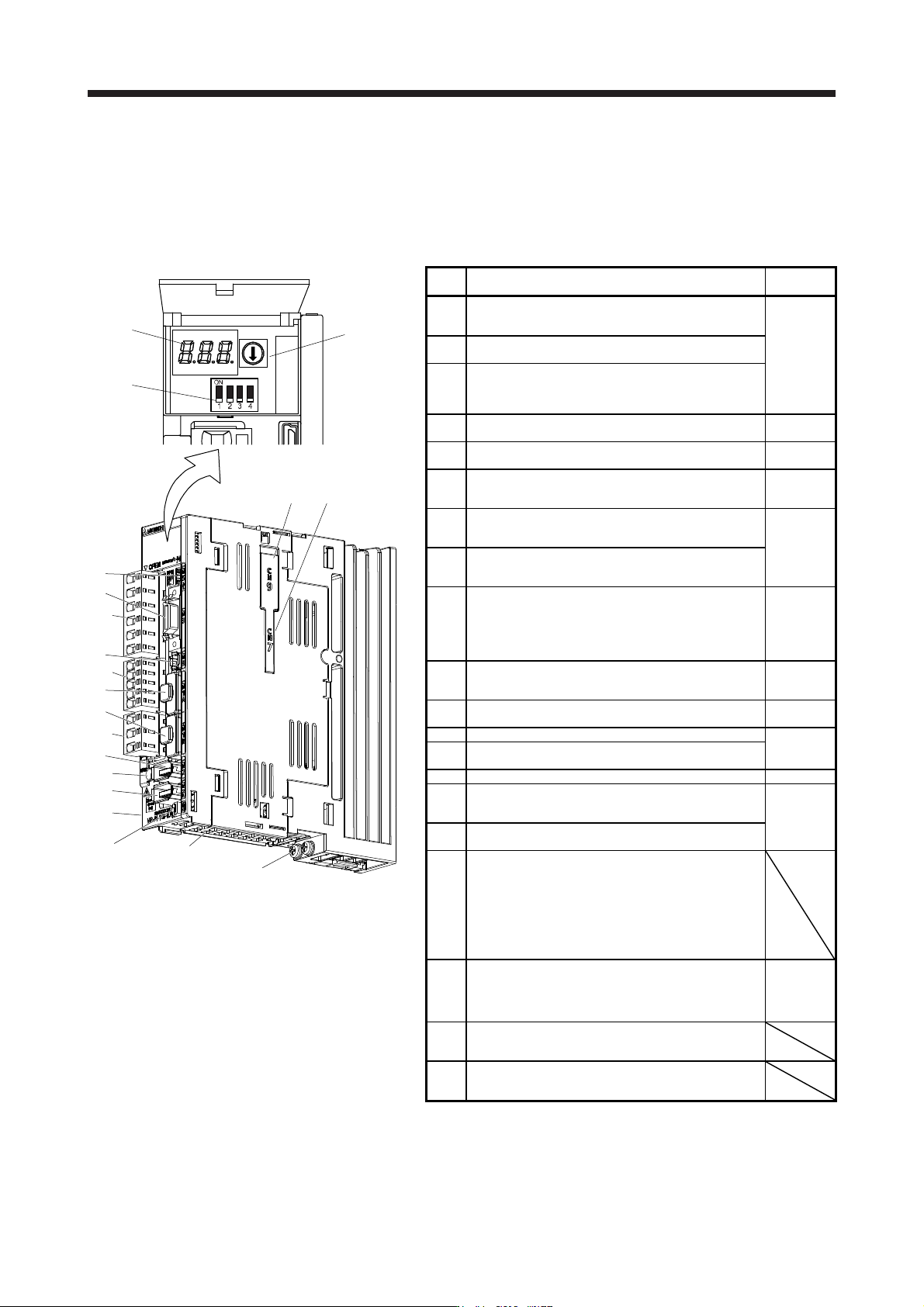
(1) 200 V class
(a) MR-J4-200B(-RJ) or less
The diagram is for MR-J4-10B-RJ.
(1)
(3)
(2)
Inside of the display cover
(5)
(18)
(13)
(10)
(17)
(9)
(6)
(7)
(11)
Bottom
(16)
(15)
(8)
(4)
(14)
Side
(12)
(19)(20)
No. Name/Application
Detailed
explanation
(1)
Display
The 3-digit, 7-segment LED shows the servo status
and the alarm number.
Section 4.3
(2)
Axis selection rotary switch (SW1)
Used to set the axis No. of servo amplifier.
(3)
Control axis setting switch (SW2)
The test operation switch, the disabling control axis
switch, and the auxiliary axis number setting switch
are available.
(4)
USB communication connector (CN5)
Connect with the personal computer.
Section
11.7
(5)
I/O signal connector (CN3)
Used to connect digital I/O signals.
Section 3.2
Section 3.4
(6)
STO input signal connector (CN8)
Used to connect MR-J3-D05 safety logic unit and
external safety relay.
Chapter 13
App. 5
(7)
SSCNET III cable connector (CN1A)
Used to connect the servo system controller or the
previous axis servo amplifier.
Section 3.2
Section 3.4
(8)
SSCNET III cable connector (CN1B)
Used to connect the next axis servo amplifier. For
the final axis, put a cap.
(9)
(Note
2)
Encoder connector (CN2)
Used to connect the servo motor encoder.
Used to connect the servo motor encoder or
external encoder. Refer to table 1.1 for the
compatible external encoders.
Section 3.4
"Servo
Motor
Instruction
Manual
(Vol. 3)"
(10)
Battery connector (CN4)
Used to connect the battery for absolute position
data backup.
Chapter 12
(11)
Battery holde
r
Install the battery for absolute position data backup.
Section
12.2
(12) Protective earth (PE) terminal
Section 3.1
Section 3.3
(13)
Main circuit power connector (CNP1)
Connect the input power supply.
(14) Rating plate Section 1.6
(15)
Control circuit power connector (CNP2)
Connect the control circuit power supply and
regenerative option.
Section 3.1
Section 3.3
(16)
Servo motor power output connector (CNP3)
Connect the servo motor.
(17)
Charge lamp
When the main circuit is charged, this will light.
While this lamp is lit, do not reconnect the cables.
The lamp may light up when only the control circuit
is powered on. Before wiring or inspection, turn off
the main circuit power and the control circuit power,
and wait for 15 minutes or more until the charge
lamp turns off. Then, check the voltage between P+
and N- using the tester, etc.
(18)
(Note
1, 2)
External encoder connector (CN2L)
Refer to table 1.1 for connections of external
encoders.
Section 3.4
"Linear
Encoder
Instruction
Manual"
(19)
Optional unit connector 1 (CN7)
This is for connecting the optional unit. This
connector is attached only on MR-J4-_B_-RJ.
(20)
Optional unit connector 2 (CN9)
This is for connecting the optional unit. This
connector is attached only on MR-J4-_B_-RJ.
Note 1. This is for MR-J4-_B-RJ servo amplifier. MR-J4-_B servo
amplifier does not have CN2L connector.
2. "External encoder" is a term for linear encoder used in the linear
servo system, load-side encoder used in the fully closed loop
system, and scale measurement encoder used with the scale
measurement function in this manual.
1. FUNCTIONS AND CONFIGURATION
1 - 25
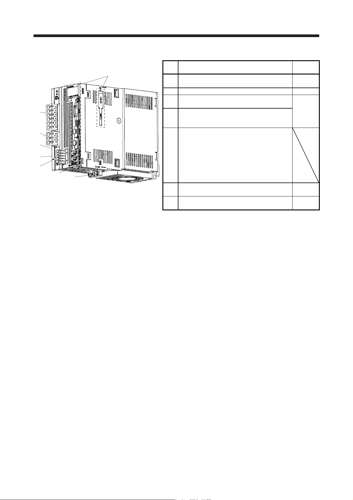
(b) MR-J4-350B(-RJ)
The broken line area is the same as
MR-J4-200B(-RJ) or less.
(1)
(3)
(2)
Side
(4)
(5)
(7)
(6)
No. Name/Application
Detailed
explanation
(1)
Main circuit power connector (CNP1)
Connect the input power supply.
Section 3.1
Section 3.3
(2) Rating plate Section 1.6
(3)
Servo motor power connector (CNP3)
Connect the servo motor.
Section 3.1
Section 3.3
(4)
Control circuit power connector (CNP2)
Connect the control circuit power supply and
regenerative option.
(5)
Charge lamp
When the main circuit is charged, this will light.
While this lamp is lit, do not reconnect the cables.
The lamp may light up when only the control circuit
is powered on. Before wiring or inspection, turn off
the main circuit power and the control circuit power,
and wait for 15 minutes or more until the charge
lamp turns off. Then, check the voltage between P+
and N- using the tester, etc.
(6)
Protective earth (PE) terminal Section 3.1
Section 3.3
(7)
Battery holder
Install the battery for absolute position data backup.
Section
12.2
1. FUNCTIONS AND CONFIGURATION
1 - 26
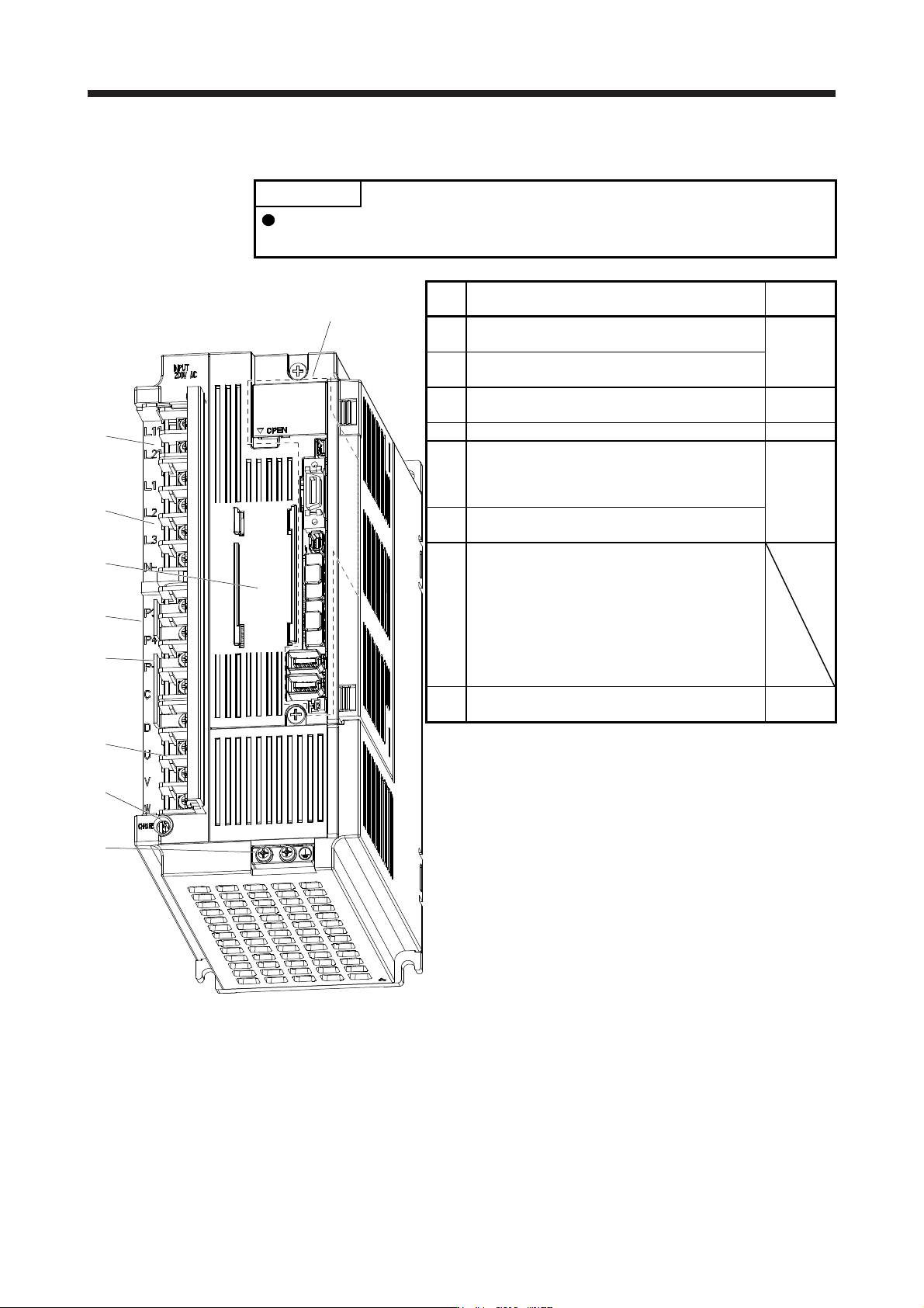
(c) MR-J4-500B(-RJ)
POINT
The servo amplifier is shown with the front cover open. The front cover cannot
be removed.
(1)
(3)
(2)
(Note)
(8)
(4)
Side
(5)
(6)
(7)
The broken line area is the same as
MR-J4-200B(-RJ) or less.
No. Name/Application
Detailed
explanation
(1)
Control circuit terminal block (TE2)
Used to connect the control circuit power supply.
Section 3.1
Section 3.3
(2)
Main circuit terminal block (TE1)
Connect the input power supply.
(3)
Battery holder
Install the battery for absolute position data backup.
Section
12.2
(4) Rating plate Section 1.6
(5)
Regenerative option/power factor improving reactor
terminal block (TE3)
Used to a connect a regenerative option and a
power factor improving DC reactor.
Section 3.1
Section 3.3
(6)
Servo motor power supply terminal block (TE4)
Connect the servo motor.
(7)
Charge lamp
When the main circuit is charged, this will light.
While this lamp is lit, do not reconnect the cables.
The lamp may light up when only the control circuit
is powered on. Before wiring or inspection, turn off
the main circuit power and the control circuit power,
and wait for 15 minutes or more until the charge
lamp turns off. Then, check the voltage between P+
and N- using the tester, etc.
(8)
Protective earth (PE) terminal Section 3.1
Section 3.3
Note. Lines for slots around the batter
y
holder are omitted from the illustration.