sh030106u.pdf - 第520页
15. USIN G A DI REC T DRIV E MOTOR 15 - 17 15.4 Charac teristic s 15.4.1 Ov erload pr otecti on char acteristic s An electr onic th erma l is bui lt in the servo ampli fier to pr otec t th e serv o amplif ier, d irect dr…
15. USING A DIRECT DRIVE MOTOR
15 - 16
(b) Speed deviation error detection
Set [Pr. PL04] to "_ _ _ 2" to enable the speed deviation error detection.
[Pr. PL04]
Speed deviation error detection enable
d
2
When you compare the model feedback speed ( 3)) and the feedback speed ( 4)) in figure 15.1, if the
deviation is more than the value of [Pr. PL06 Speed deviation error detection level] (1 r/min to 2000
r/min), [AL. 42.2 Servo control error by speed deviation] will occur and the linear servo motor will
stop. The initial value of this detection level is 100 r/min. Replace the set value as required.
(c) Torque deviation error detection level
Set [Pr. PL04] to "_ _ _ 4" to enable the torque deviation error detection.
[Pr. PL04]
Torque deviation error detection enabled
4
When you compare the command torque ( 5)) and the feedback torque ( 6)) in figure 15.1, if the
deviation is more than the value of [Pr. PL07 Torque/thrust deviation error detection level] (1% to
1000%), [AL. 42.3 Servo control error by torque/thrust deviation] will occur and the linear servo motor
will stop. The initial value of this detection level is 100%. Replace the set value as required.
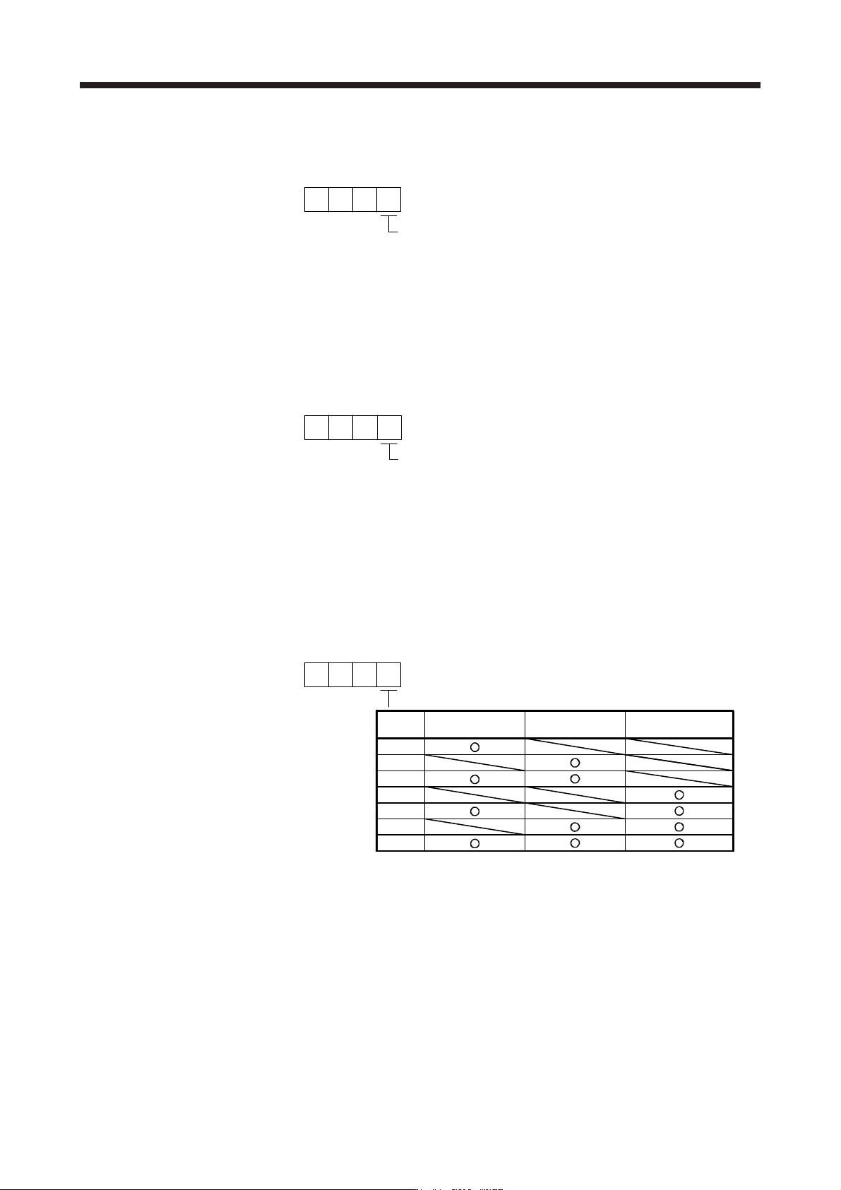
(d) Detecting multiple deviation errors
When setting [Pr. PL04] as shown below, multiple deviation errors can be detected. For the error
detection methods, refer to (1) (a), (b), (c) in this section.
[Pr. PL04]
Position deviation
error detection
Setting
value
Speed deviation
error detection
Torque deviation
error detection
1
5
6
7
3
2
4

15. USING A DIRECT DRIVE MOTOR
15 - 17
15.4 Characteristics
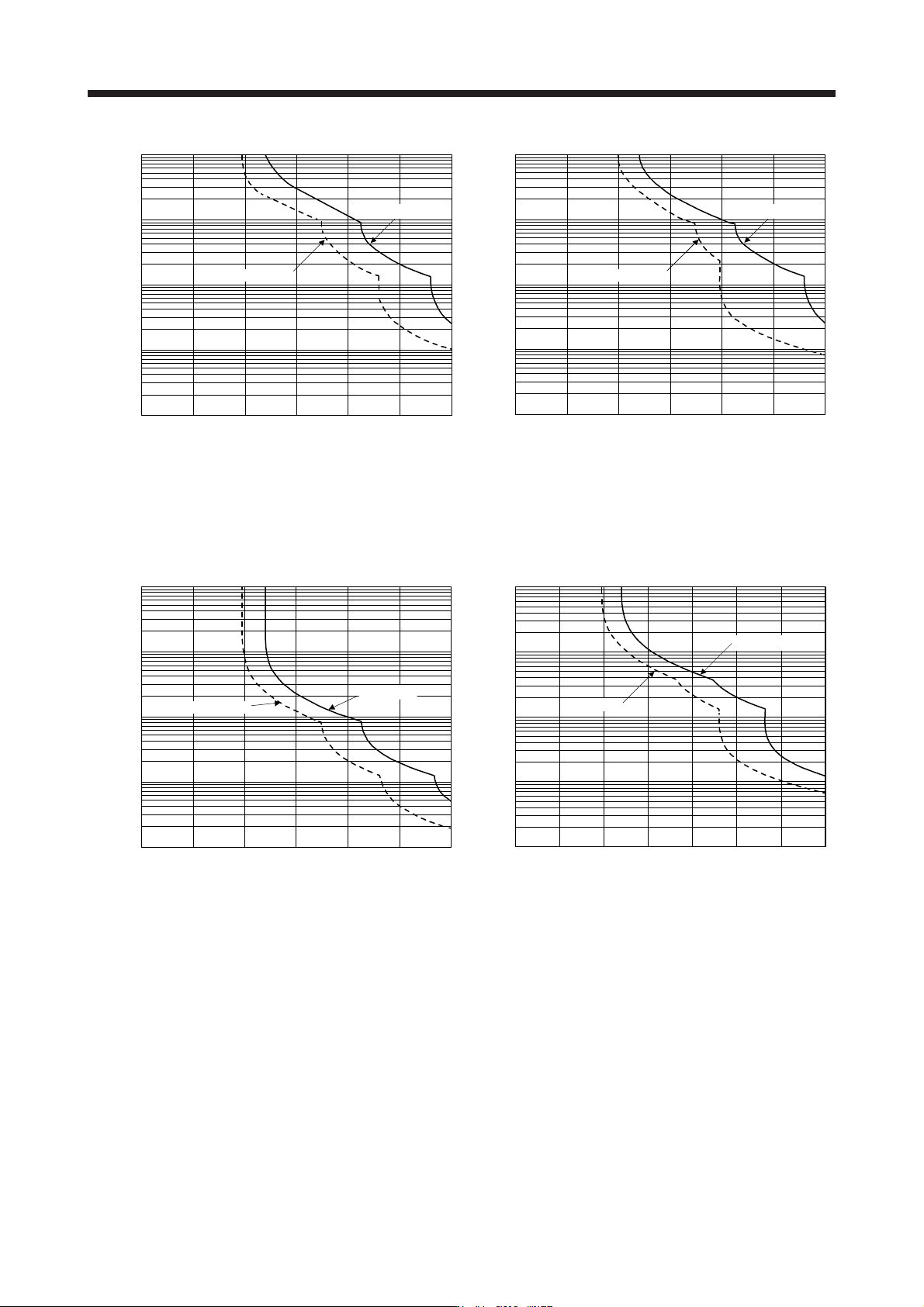
15.4.1 Overload protection characteristics
An electronic thermal is built in the servo amplifier to protect the servo amplifier, direct drive motor, and direct
drive motor power wires from overloads.
[AL. 50 Overload 1] occurs if overload operation performed is above the electronic thermal relay protection
curve shown in Fig. 15.2 [AL. 51 Overload 2] occurs if the maximum current is applied continuously for
several seconds due to machine collision, etc. Use the equipment on the left-side area of the continuous or
broken line in the graph.
When unbalanced torque is generated, such as in a vertical lift machine, the unbalanced torque of the
machine should be kept at 70% or lower of the motor's rated torque.
This servo amplifier has solid-state direct drive motor overload protection for each axis. (The direct drive
motor overload current (full load current) is set on the basis of 120% rated current of the servo amplifier.)
15. USING A DIRECT DRIVE MOTOR
15 - 18
1000
100
10
1
0.1
0 50 150 200 250 300
100
Servo-lock
Operation time [s]
(Note) Load ratio [%]
Operating
TM-RFM002C20/TM-RFM004C20/
TM-RFM006C20/TM-RFM006E20/
TM-RFM012E20/TM-RFM018E20/
TM-RFM012G20/TM-RFM040J10
1000
100
10
1
0.1
0 50 150 200 250 300100
Servo-lock
Operation time [s]
(Note) Load ratio [%]
Operating
TM-RFM120J10
10000
1000
100
10
1
0 50 150 200 250 300100
Servo-lock
Operation time [s]
(Note) Load ratio [%]
Operating
TM-RFM048G20/TM-RFM072G20/
TM-RFM240J10
0 50 100 150 200 250 300 350
1000
100
10
1
0.1
Operation time [s]
Servo-lock
(Note) Load ratio [%]
Operating
TM-RG2M002C30/TM-RU2M002C30/
TM-RG2M004E30/TM-RU2M004E30/
TM-RG2M009G30/TM-RU2M009G30
Note. If operation that generates torque more than 100% of the rating is performed with an abnormally high frequency in a direct drive
motor stop status (servo-lock status) or in a 50 r/min or less low-speed operation status, the servo amplifier may malfunction
re
g
ardless of the electronic thermal rela
y
protection.
Fig. 15.2 Electronic thermal relay protection characteristics