sh030106u.pdf - 第237页
7. SPEC IAL ADJUSTMEN T FUNCT IONS 7 - 8 7.1.4 Low-p ass fil ter (1) Function When a ball sc rew or t he lik e is use d, reson ance o f hig h freque ncy ma y occur as t he re sponse le vel of the servo system is increase…
7. SPECIAL ADJUSTMENT FUNCTIONS
7 - 7
7.1.3 Shaft resonance suppression filter
POINT
This filter is set properly by default according to servo motor you use and load
moment of inertia. It is recommended that [Pr. PB23] be set to "_ _ _ 0"
(automatic setting) because changing "Shaft resonance suppression filter
selection" in [Pr. PB23] or [Pr. PB17 Shaft resonance suppression filter] may
lower the performance.
(1) Function
When a load is mounted to the servo motor shaft, resonance by shaft torsion during driving may
generate a mechanical vibration at high frequency. The shaft resonance suppression filter suppresses
the vibration.
When you select "Automatic setting", the filter will be set automatically on the basis of the motor you use
and the load to servo motor inertia ratio. The disabled setting increases the response of the servo
amplifier for high resonance frequency.
(2) Parameter
Set "Shaft resonance suppression filter selection" in [Pr. PB23].
[Pr. PB23]
Shaft resonance suppression filter selection
0: Automatic setting
1: Manual setting
2: Disabled
000
To set [Pr. PB17 Shaft resonance suppression filter] automatically, select "Automatic setting".
To set [Pr. PB17 Shaft resonance suppression filter] manually, select "Manual setting". The setting
values are as follows.
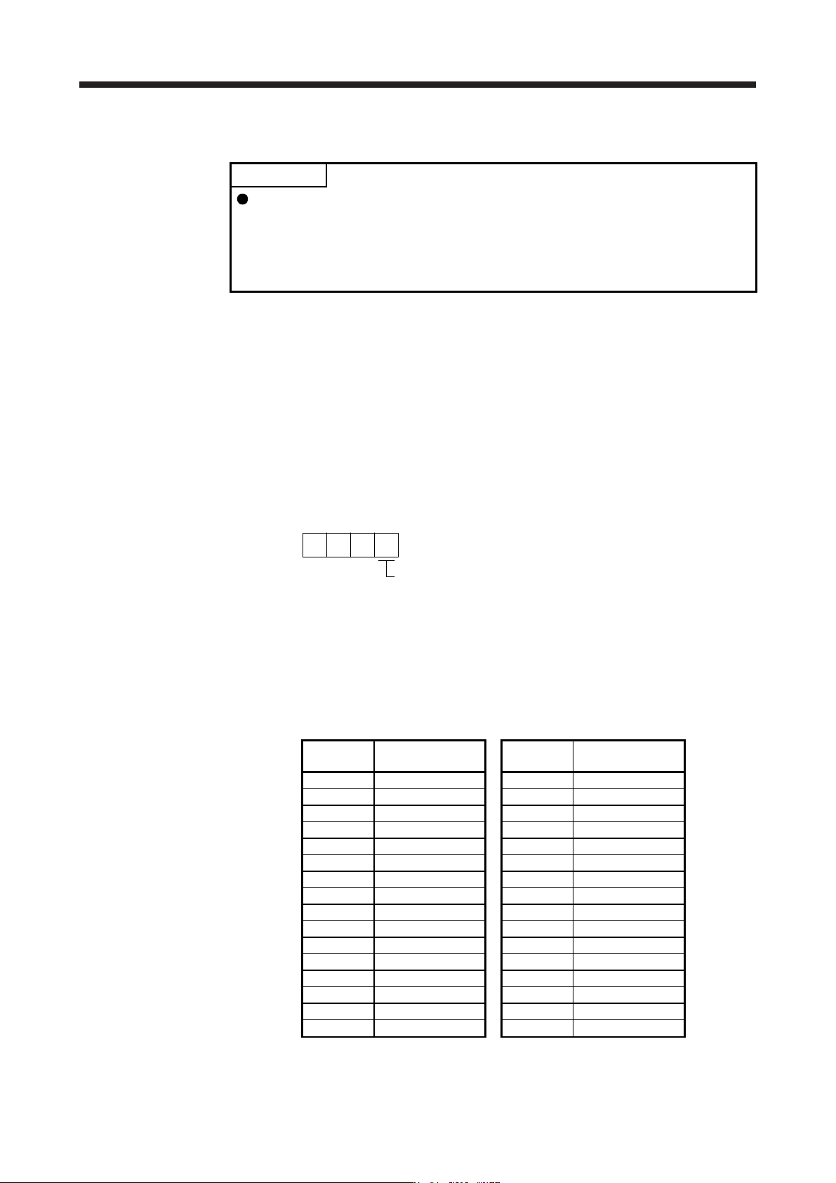
Shaft resonance suppression filter setting frequency selection
Setting
value
Frequency [Hz]
Setting
value
Frequency [Hz]
_ _ 0 0 Disabled _ _ 1 0 562
_ _ 0 1 Disabled _ _ 1 1 529
_ _ 0 2 4500 _ _ 1 2 500
_ _ 0 3 3000 _ _ 1 3 473
_ _ 0 4 2250 _ _ 1 4 450
_ _ 0 5 1800 _ _ 1 5 428
_ _ 0 6 1500 _ _ 1 6 409
_ _ 0 7 1285 _ _ 1 7 391
_ _ 0 8 1125 _ _ 1 8 375
_ _ 0 9 1000 _ _ 1 9 360
_ _ 0 A 900 _ _ 1 A 346
_ _ 0 B 818 _ _ 1 B 333
_ _ 0 C 750 _ _ 1 C 321
_ _ 0 D 692 _ _ 1 D 310
_ _ 0 E 642 _ _ 1 E 300
_ _ 0 F 600 _ _ 1 F 290
7. SPECIAL ADJUSTMENT FUNCTIONS
7 - 8
7.1.4 Low-pass filter
(1) Function
When a ball screw or the like is used, resonance of high frequency may occur as the response level of
the servo system is increased. To prevent this, the low-pass filter is enabled for a torque command as a
default. The filter frequency of the low-pass filter is automatically adjusted to the value in the following
equation.
Filter frequency ([rad/s]) =
1 + GD2
VG2
× 10
However, when an automatically adjusted value is smaller than VG2, the filter frequency will be the VG2
value. To set [Pr. PB18] manually, select "Manual setting (_ _ 1 _)" of "Low-pass filter selection" in [Pr.
PB23].
(2) Parameter
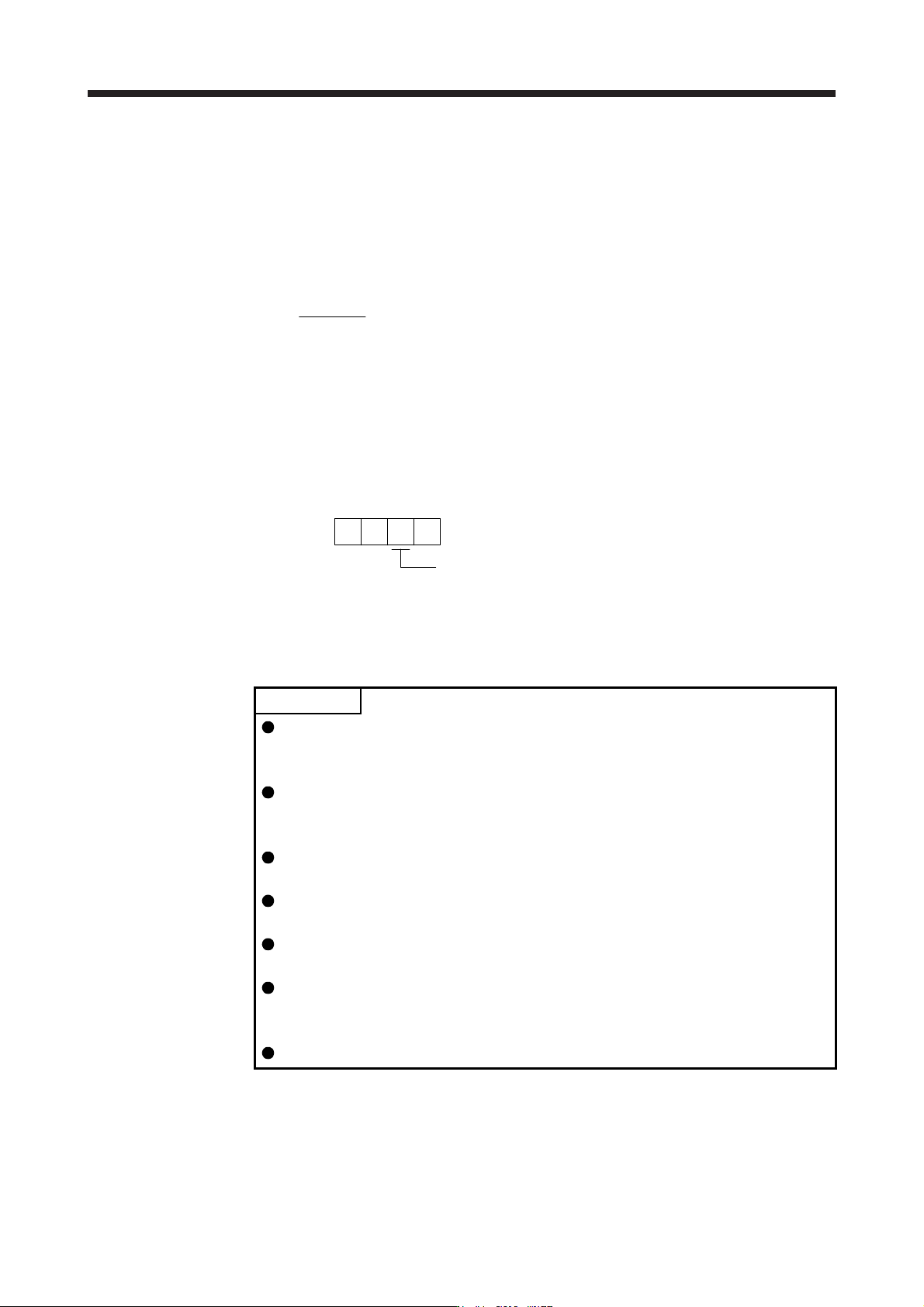
Set "Low-pass filter selection" in [Pr. PB23].
[Pr. PB23]
Low-pass filter selection
0: Automatic setting
1: Manual setting
2: Disabled
00 0
7.1.5 Advanced vibration suppression control II
POINT
The function is enabled when "Gain adjustment mode selection" in [Pr. PA08] is
"Auto tuning mode 2 (_ _ _ 2)", "Manual mode (_ _ _ 3)", or "2 gain adjustment
mode 2 (_ _ _ 4)".
The machine resonance frequency supported in the vibration suppression
control tuning mode is 1.0 Hz to 100.0 Hz. As for the vibration out of the range,
set manually.
Stop the servo motor before changing the vibration suppression control-related
parameters. Otherwise, it may cause an unexpected operation.
For positioning operation during execution of vibration suppression control
tuning, provide a stop time to ensure a stop after vibration damping.
Vibration suppression control tuning may not make normal estimation if the
residual vibration at the servo motor side is small.
Vibration suppression control tuning sets the optimum parameter with the
currently set control gains. When the response setting is increased, set vibration
suppression control tuning again.
When using the vibration suppression control 2, set "_ _ _ 1" in [Pr. PA24].
7. SPECIAL ADJUSTMENT FUNCTIONS
7 - 9
(1) Function
Vibration suppression control is used to further suppress load-side vibration, such as work-side vibration
and base shake. The servo motor-side operation is adjusted for positioning so that the machine does not
vibrate.
Vibration suppression: off (normal)
Servo motor side
Load side
t
Position
Vibration suppression control: on
Servo motor side
Load side
Position
t
When the advanced vibration suppression control II ([Pr. PB02 Vibration suppression control tuning
mode]) is executed, the vibration frequency at load side is automatically estimated to suppress machine
side vibration two times at most.
In the vibration suppression control tuning mode, this mode shifts to the manual setting after the
positioning operation is performed the predetermined number of times. For manual setting, adjust the
vibration suppression control 1 with [Pr. PB19] to [Pr. PB22] and vibration suppression control 2 with [Pr.
PB52] to [Pr. PB55].
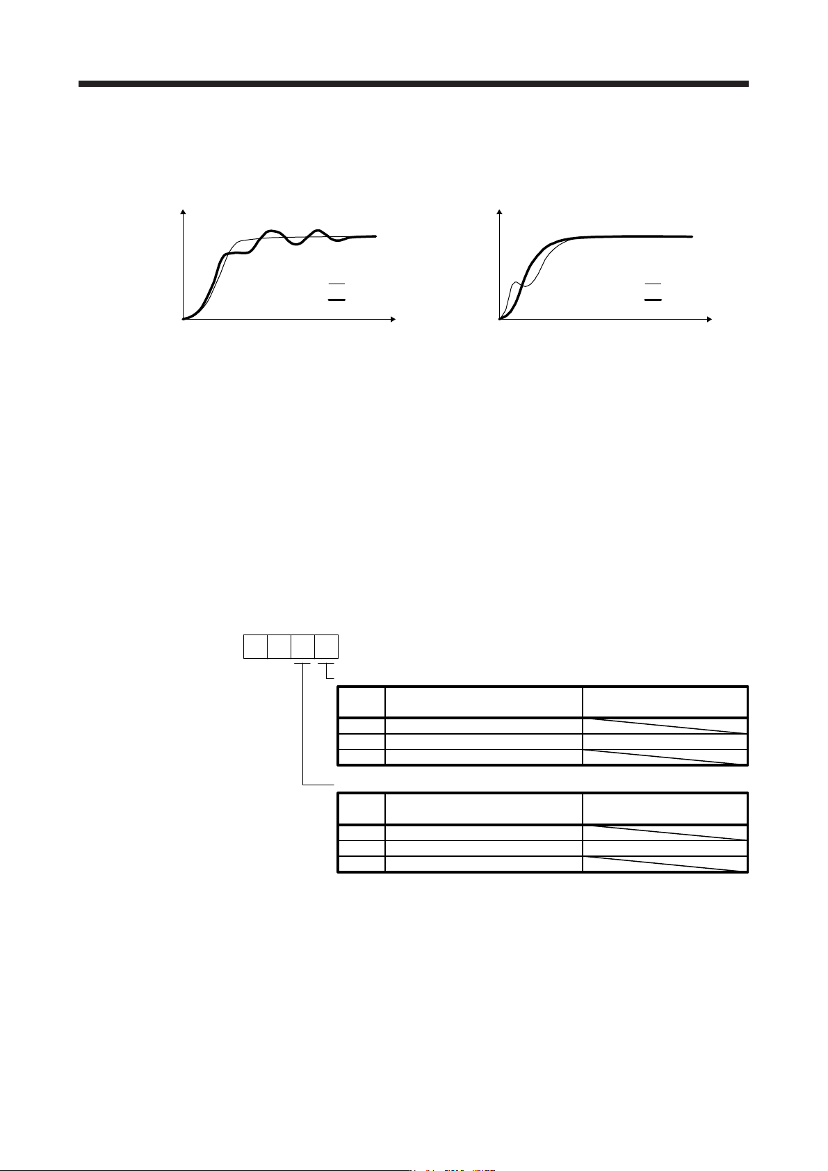
(2) Parameter
Set [Pr. PB02 Vibration suppression control tuning mode (advanced vibration suppression control II)].
When you use a vibration suppression control, set "Vibration suppression control 1 tuning mode
selection". When you use two vibration suppression controls, set "Vibration suppression control 2 tuning
mode selection" in addition.
[Pr. PB02]
Vibration suppression control 1 tuning mode
00
_ _ _ 0
_ _ _ 1
_ _ _ 2
Setting
value
Vibration suppression control 1
tuning mode selection
Disabled
Automatic setting
Manual setting
PB19/PB20/PB21/PB22
Automatically set parameter
Vibration suppression control 2 tuning mode
_ _ 0 _
_ _ 1 _
_ _ 2 _
Setting
value
Vibration suppression control 2
tuning mode selection
Disabled
Automatic setting
Manual setting
PB52/PB53/PB54/PB55
Automatically set parameter