sh030106u.pdf - 第513页
15. USIN G A DI REC T DRIV E MOTOR 15 - 10 (3) Operation at the m agnetic pole de tection WARNING Note that the mag netic po le detec tion aut omatic ally s tarts simu lt aneous ly with the turning-on of the s ervo-on c …
15. USING A DIRECT DRIVE MOTOR
15 - 9
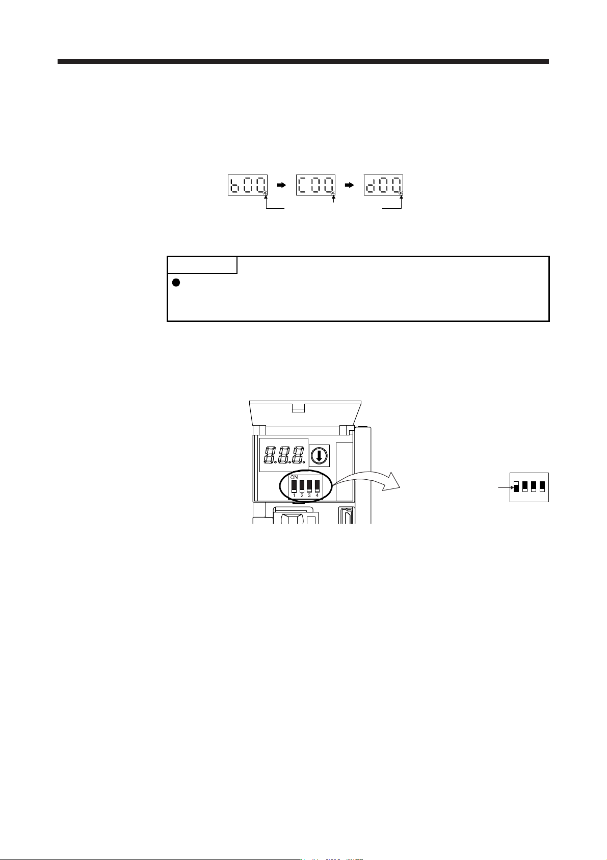
(c) State transition of the servo amplifier display (3-digit, 7-segment LED) at the magnetic pole detection
When the magnetic pole detection with MR Configurator2 is normally executed, the servo amplifier
display (3-digit, 7-segment LED) shows the state as below.
The decimal point blinks.
Servo-off status
During the
magnetic
pole detection
Magnetic pole
detection
completed
(Servo-on status)
(2) Preparation for the magnetic pole detection
POINT
When the test operation mode is selected with the test operation select switch
(SW2-1), the SSCNET III/H communication for the servo amplifier in the test
operation mode and the following servo amplifiers is blocked.
For the magnetic pole detection, use the test operation mode (positioning operation) of MR
Configurator2. Turn off the servo amplifier power, and set the test operation select switch (SW2-1) and
the disabling control axis switch (SW2-2, SW2-3, and SW2-4) as shown below. Turning on the power
enables the test operation mode.
Set SW2-1 to "ON (up)".
1
ON
2 3 4
15. USING A DIRECT DRIVE MOTOR
15 - 10
(3) Operation at the magnetic pole detection
WARNING
Note that the magnetic pole detection automatically starts simultaneously with the
turning-on of the servo-on command.
CAUTION
If the magnetic pole detection is not executed properly, the direct drive motor may
operate unexpectedly.
POINT
Establish the machine configuration using FLS (Upper stroke limit) and RLS
(Lower stroke limit). Otherwise, the machine may be damaged due to a collision.
At the magnetic pole detection, whether the motor rotates in the forward or
reverse direction is unpredictable.
Depending on the setting value of [Pr. PL09 Magnetic pole detection voltage
level], an overload, overcurrent, magnetic pole detection alarm, or others may
occur.
When performing the positioning operation from a controller, use the sequence
which confirms the normal completion of the magnetic pole detection and the
servo-on status, then outputs the positioning command. If the controller outputs
the positioning command before RD (Ready) turns on, the command may not be
accepted or a servo alarm may occur.
After the magnetic pole detection, check the positioning accuracy with the test
operation (positioning operation function) of MR Configurator2.
The accuracy of the magnetic pole detection improves with no load.
(a) Incremental system
POINT
For the incremental system, the magnetic pole detection is required every time
the power is turned on.
By turning on the servo-on command from the controller after the power-on, the magnetic pole
detection is automatically carried out. Therefore, there is no need to set the parameter (first digit of
[Pr. PL01]) for executing the magnetic pole detection.
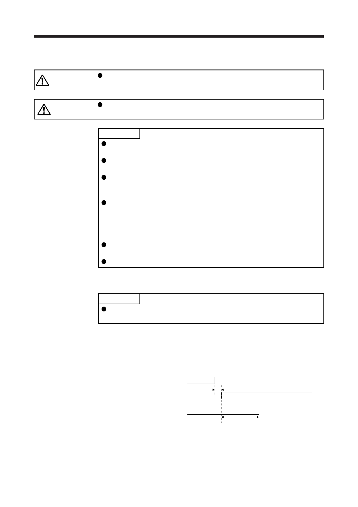
1) Timing chart
15 s or less
ON
OFF
ON
OFF
ON
OFF
95 ms
Servo-on command
Base circuit
RD (Ready)
Magnetic pole detection time (Note)
Note. The magnetic pole detection time indicates the operation time when FLS (Upper
stroke limit
)
and RLS
(
Lower stroke limit
)
are on.
15. USING A DIRECT DRIVE MOTOR
15 - 11
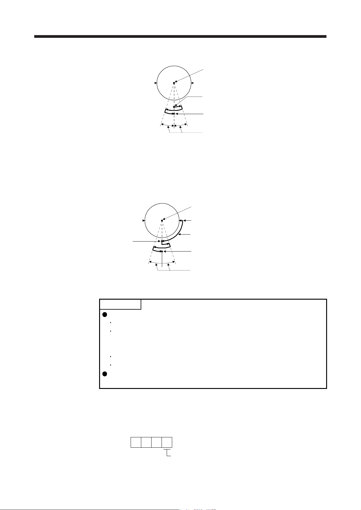
2) Direct drive motor movement (when FLS and RLS are on)
Magnetic pole detection completion position
Servo-on position (Magnetic pole detection start position)
Center of direct drive motor rotation part
FLS (Note)
(Note) RLS
10 degrees or less
Note. When you turn off FLS (Upper stroke limit) or RLS (Lower stroke limit) during the
magnetic pole detection, the magnetic pole detection is carried on to the opposite
direction. When FLS and RLS are off, [AL. 27 Initial magnetic pole detection error]
occurs.
3) Direct drive motor movement (when FLS or RLS is off)
When FLS or RLS is off at servo-on, the magnetic pole detection is carried out as follows.
Magnetic pole detection completion position
Magnetic pole detection
start position
After the machine moves to the position where the stroke limit
(FLS or RLS) is set, the magnetic pole detection starts.
Servo-on position
Center of direct drive motor rotation part
FLS
RLS
10 degrees or less
(b) Absolute position detection system
POINT
The magnetic pole detection is required in the following timings.
When the system is set up (at the first startup of equipment)
When the Z-phase pulse of the direct drive motor is not turned on at the
system setup (When the Z-phase pulse of the direct drive motor can be turned
on manually, the magnetic pole detection is not required.)
After a direct drive motor is replaced
When [AL. 25 Absolute position erased] has occurred
Turn on the Z-phase pulse of the direct drive motor in JOG operation from the
controller after the magnetic pole detection.
Perform the magnetic pole detection in the following procedure.
1) Set [Pr. PL01 Linear servo motor/DD motor function selection 1] to "_ _ _ 1" (Magnetic pole
detection at first servo-on).
[Pr. PL01]
Magnetic pole detection at first servo-on (initial value)
1