sh030106u.pdf - 第9页
A - 8 «Wiring » Wires mentio ned in this I nstruc tion Ma nual are s elect ed base d o n the ambie nt te mperature of 40 °C. «U.S. cus tomary units» U.S. customary units are not show n in th is manua l. Convert th e valu…
A - 7
EEP-ROM life
The number of write times to the EEP-ROM, which stores parameter settings, etc., is limited to 100,000. If
the total number of the following operations exceeds 100,000, the servo amplifier may malfunction when the
EEP-ROM reaches the end of its useful life.
Write to the EEP-ROM due to parameter setting changes
Write to the EEP-ROM due to device changes
STO function of the servo amplifier
The servo amplifier complies with safety integrity level 3 (SIL 3) of the IEC 61508:2010 functional safety
standard.
Refer to app. 14 for schedule.
When using the STO function of the servo amplifier, refer to chapter 13.
For the MR-J3-D05 safety logic unit, refer to app. 5.
Compliance with global standards
For the compliance with global standards, refer to app. 4.
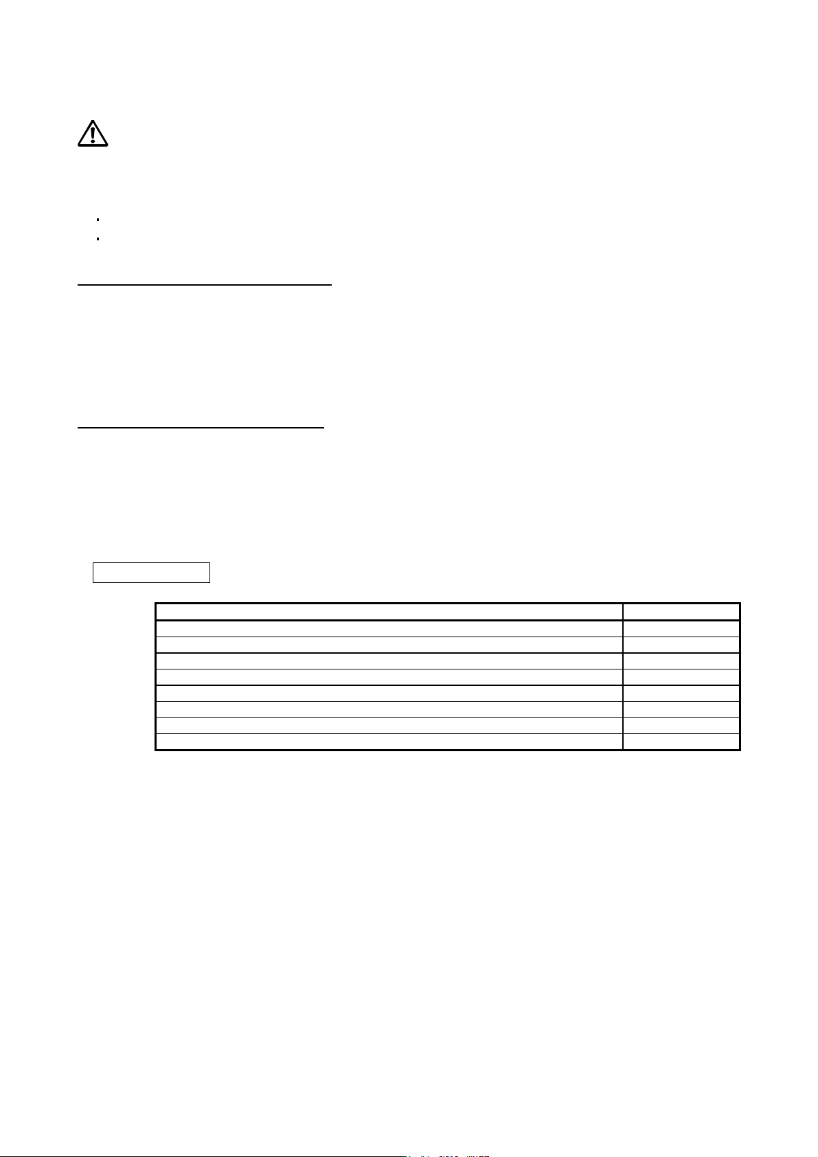
«About the manuals»
You must have this Instruction Manual and the following manuals to use this servo. Ensure to prepare
them to use the servo safely.
Relevant manuals
Manual name Manual No.
MELSERVO MR-D30 Instruction Manual (Note 5) SH(NA)030132ENG
MELSERVO MR-CV_/MR-CR55K_/MR-J4-DU_(-RJ) Instruction Manual (Note 6) SH(NA)030153ENG
MELSERVO-J4 Servo Amplifier Instruction Manual (Troubleshooting) SH(NA)030109ENG
MELSERVO Servo Motor Instruction Manual (Vol. 3) (Note 1) SH(NA)030113ENG
MELSERVO Linear Servo Motor Instruction Manual (Note 2) SH(NA)030110ENG
MELSERVO Direct Drive Motor Instruction Manual (Note 3) SH(NA)030112ENG
MELSERVO Linear Encoder Instruction Manual (Note 2, 4) SH(NA)030111ENG
MELSERVO EMC Installation Guidelines IB(NA)67310ENG
Note 1. It is necessar
y
for usin
g
a rotar
y
servo motor.
2. It is necessar
y
for usin
g
a linear servo motor.
3. It is necessar
y
for usin
g
a direct drive motor.
4. It is necessar
y
for usin
g
a full
y
closed loop s
y
stem.
5. It is necessar
y
for usin
g
an MR-D30 functional safet
y
unit.
6. It is necessary for using an MR-CV_ power regeneration converter unit/MR-CR_ resistance regeneration
converter unit, and MR-J4-DU_B_
(
-RJ
)
drive unit.
A - 8
«Wiring»
Wires mentioned in this Instruction Manual are selected based on the ambient temperature of 40 °C.
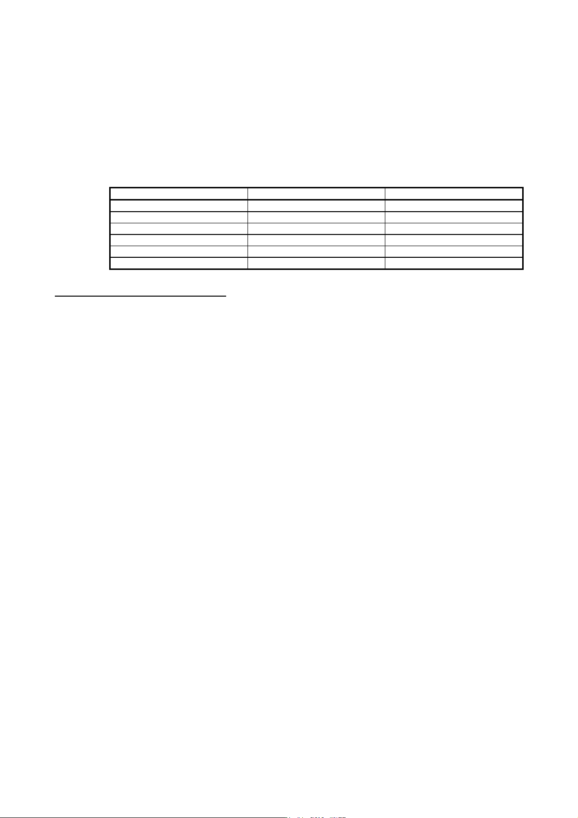
«U.S. customary units»
U.S. customary units are not shown in this manual. Convert the values if necessary according to the
following table.
Quantity SI (metric) unit U.S. customary unit
Mass 1 [kg] 2.2046 [lb]
Length 1 [mm] 0.03937 [inch]
Torque 1 [N•m] 141.6 [oz•inch]
Moment of inertia 1 [(× 10
-4
kg•m
2
)] 5.4675 [oz•inch
2
]
Load (thrust load/axial load) 1 [N] 0.2248 [lbf]
Temperature N [°C] × 9/5 + 32 N [°F]
Global standards and regulations
Compliance with the indicated global standards and regulations is current as of the release date of this
manual. Some standards and regulations may have been modified or withdrawn.

1
CONTENTS
1. FUNCTIONS AND CONFIGURATION 1- 1 to 1-52
1.1 Summary ........................................................................................................................................... 1- 1
1.2 Function block diagram ..................................................................................................................... 1- 3
1.3 Servo amplifier standard specifications ........................................................................................... 1-13
1.4 Combinations of servo amplifiers and servo motors ........................................................................ 1-19
1.5 Function list ...................................................................................................................................... 1-21
1.6 Model designation ............................................................................................................................ 1-23
1.7 Structure........................................................................................................................................... 1-24
1.7.1 Parts identification ..................................................................................................................... 1-24
1.7.2 Removal and reinstallation of the front cover ............................................................................ 1-37
1.8 Configuration including peripheral equipment ................................................................................. 1-39
2. INSTALLATION 2- 1 to 2- 8
2.1 Installation direction and clearances ................................................................................................. 2- 2
2.2 Keeping out of foreign materials ....................................................................................................... 2- 4
2.3 Encoder cable stress ........................................................................................................................ 2- 4
2.4 SSCNET III cable laying ................................................................................................................... 2- 4
2.5 Inspection items ................................................................................................................................ 2- 6
2.6 Parts having service life .................................................................................................................... 2- 7
2.7 Restrictions when using this product at altitude exceeding 1000 m and up to 2000 m
above sea level ................................................................................................................................. 2- 8
3. SIGNALS AND WIRING 3- 1 to 3-48
3.1 Input power supply circuit ................................................................................................................. 3- 3
3.1.1 200 V class ................................................................................................................................. 3- 4
3.1.2 400 V class ................................................................................................................................ 3-10
3.1.3 100 V class ................................................................................................................................ 3-14
3.2 I/O signal connection example ......................................................................................................... 3-15
3.2.1 For sink I/O interface ................................................................................................................. 3-15
3.2.2 For source I/O interface ............................................................................................................ 3-17
3.3 Explanation of power supply system ............................................................................................... 3-18
3.3.1 Signal explanations ................................................................................................................... 3-18
3.3.2 Power-on sequence .................................................................................................................. 3-19
3.3.3 Wiring CNP1, CNP2, and CNP3 ............................................................................................... 3-20
3.4 Connectors and pin assignment ...................................................................................................... 3-24
3.5 Signal (device) explanations ............................................................................................................ 3-26
3.5.1 Input device ............................................................................................................................... 3-26
3.5.2 Output device ............................................................................................................................ 3-27
3.5.3 Output signal ............................................................................................................................. 3-28
3.5.4 Power supply ............................................................................................................................. 3-28
3.6 Forced stop deceleration function .................................................................................................... 3-29
3.6.1 Forced stop deceleration function ............................................................................................. 3-29
3.6.2 Base circuit shut-off delay time function ................................................................................... 3-31
3.6.3 Vertical axis freefall prevention function.................................................................................... 3-32
3.6.4 Residual risks of the forced stop function (EM2) ...................................................................... 3-32
3.7 Alarm occurrence timing chart ......................................................................................................... 3-33