sh030106u.pdf - 第29页
1. FUNCTI ONS AND CONF IGURATION 1 - 12 (3) 100 V clas s Model position Current control Actual position control Actual speed control Virtual motor Virtual encoder L11 L21 Encoder N- CD L2 L1 Dynamic brake circuit Current…

1. FUNCTIONS AND CONFIGURATION
1 - 11
Note 1. Refer to section 1.3 for the power suppl
y
specification.
2. MR-J4 servo amplifier has P3 and P4 in the upstream of the inrush current suppression circuit. They are different from P1 and
P2 of MR-J3 servo amplifiers.
3. This is for MR-J4-
_
B4-RJ servo amplifier. MR-J4-
_
B4 servo amplifier does not have CN2L connector.
4. Use an external dynamic brake for this servo amplifier. Failure to do so will cause an accident because the servo motor does
not stop immediately but coasts at an alarm occurrence for which the servo motor does not decelerate to stop. Ensure the
safet
y
in the entire equipment. For alarms for which the servo motor does not decelerate to stop, refer to chapter 8.
5. The power factor improving AC reactor can also be used. In this case, the power factor improving DC reactor cannot be used.
When not usin
g
the power factor improvin
g
DC reactor, short P3 and P4.
6. The external dynamic brake cannot be used for compliance with SEMI-F47 standard. Do not assign DB (Dynamic brake
interlock) in [Pr. PD07] to [Pr. PD09]. Failure to do so will cause the servo amplifier to become servo-off when an
instantaneous power failure occurs.
1. FUNCTIONS AND CONFIGURATION
1 - 12
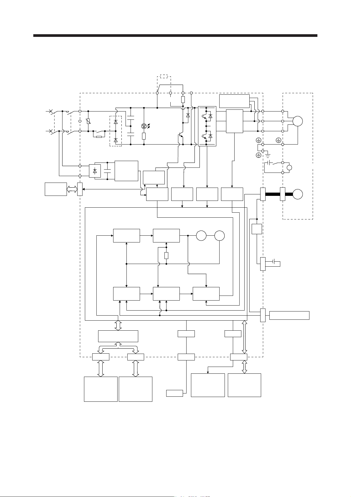
(3) 100 V class
Model position
Current
control
Actual
position
control
Actual
speed
control
Virtual
motor
Virtual
encoder
L11
L21
Encoder
N-CD
L2
L1
Dynamic brake
circuit
Current
detection
Overcurrent
protection
Voltage
detection
(Note 2)
Power
supply
MCMCCB
Base
amplifier
STO
circuit
CN5
USB
USB
Personal
computer
Servo system
controller or
servo amplifier
Servo
amplifier
or cap
CN1A CN1B
D/A
Analog monitor
(two channel)
Position
command
input
CN3
Servo amplifier
U
V
W
U
V
W
Diode stack
Relay
P+
+
+
B
RA
24 V DC
B1
B2
Battery
(for absolute position
detection system)
CN4
STO
switch
Model speed Model torque
M
CN2
CN8
Control
circuit
power
supply
Model
position
control
Model
speed
control
IF Control
Servo motor
Charge
lamp
Regene-
rative TR
Current
encoder
Digital I/O
control
Regenerative
option
U
Step-
down
circuit
External encoder
CN2L
(Note 3)
+
Electromagnetic
brake
(Note 1)
Note 1. The built-in re
g
enerative resistor is not provided for MR-J4-10B1
(
-RJ
)
.
2. Refer to section 1.3 for the power suppl
y
specifications.
3. This is for MR-J4-
_
B1-RJ servo amplifier. MR-J4-
_
B1 servo amplifier does not have CN2L connector.
1. FUNCTIONS AND CONFIGURATION
1 - 13
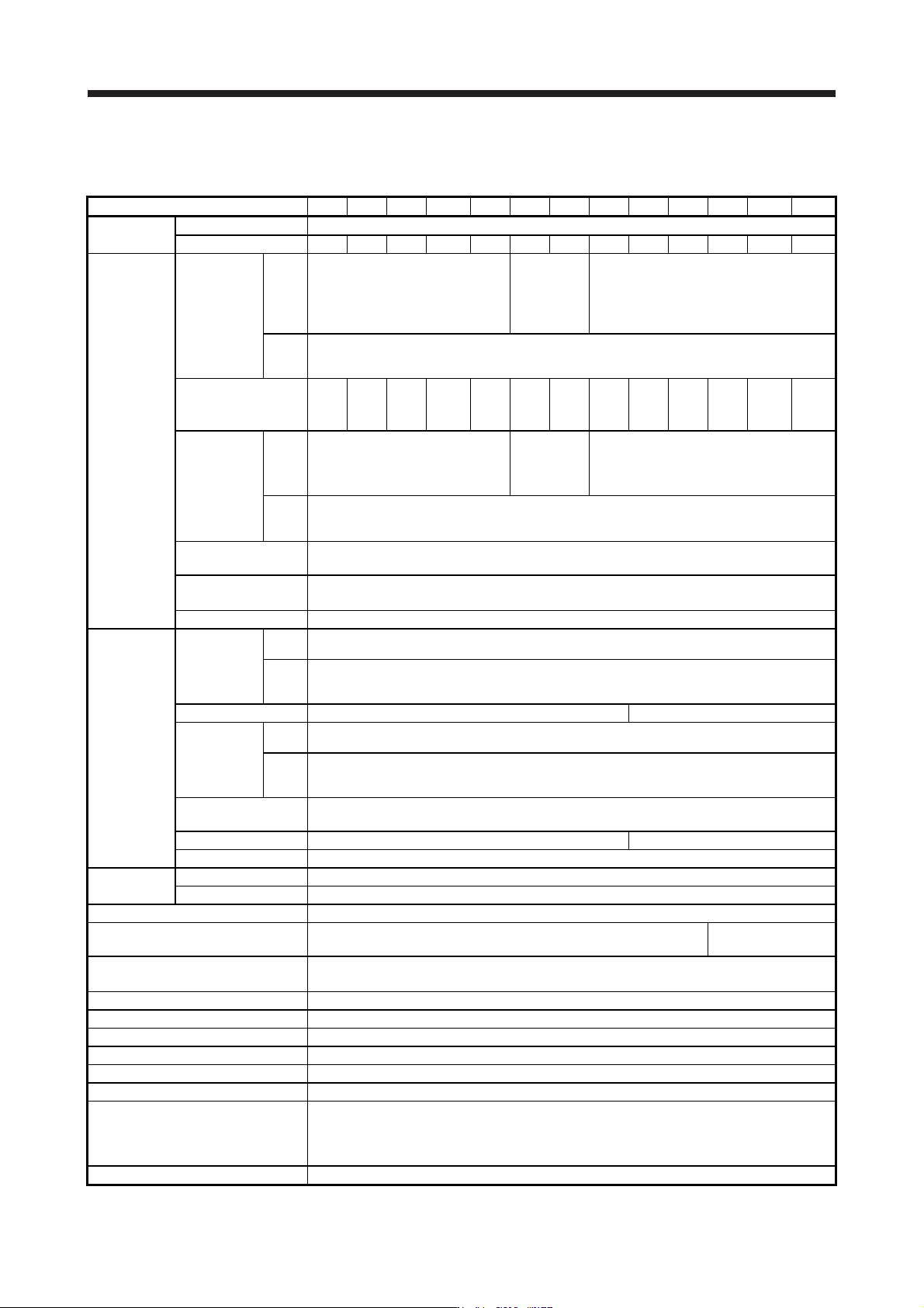
1.3 Servo amplifier standard specifications
(1) 200 V class
Model: MR-J4-_(-RJ) 10B 20B 40B 60B 70B 100B 200B 350B 500B 700B 11KB 15KB 22KB
Output
Rated voltage 3-phase 170 V AC
Rated current [A] 1.1 1.5 2.8 3.2 5.8 6.0 11.0 17.0 28.0 37.0 68.0 87.0 126.0
Main circuit
power supply
input
Voltage/
Frequency
At AC
input
3-phase or 1-phase
200 V AC to 240 V AC, 50 Hz/60 Hz
3-phase or 1-
phase 200 V
AC to 240 V
AC, 50 Hz/60
Hz (Note 13)
3-phase 200 V AC to 240 V AC, 50 Hz/60 Hz
At DC
input
(Note 16)
283 V DC to 340 V DC
Rated current
(Note 11)
[A]
0.9
(1.5)
1.5
(2.5)
2.6
(4.5)
3.2
(5.0)
(Note 6)
3.8
(6.5)
5.0
(10.5)
10.5
(15.8)
16.0 21.7 28.9 46.0 64.0 95.0
Permissible
voltage
fluctuation
At AC
input
3-phase or 1-phase
170 V AC to 264 V AC
3-phase or 1-
phase 170 V
AC to 264 V
AC (Note 13)
3-phase 170 V AC to 264 V AC
At DC
input
(Note 16)
241 V DC to 374 V DC
Permissible frequency
fluctuation
Within ±5%
Power supply capacity
[kVA]
Refer to section 10.2.
Inrush current [A] Refer to section 10.5.
Control circuit
power supply
input
Voltage/
Frequency
At AC
input
1-phase 200 V AC to 240 V AC, 50 Hz/60 Hz
At DC
input
(Note 16)
283 V DC to 340 V DC
Rated current [A] 0.2 0.3
Permissible
voltage
fluctuation
At AC
input
1-phase 170 V AC to 264 V AC
At DC
input
(Note 16)
241 V DC to 374 V DC
Permissible frequency
fluctuation
Within ±5%
Power consumption [W] 30 45
Inrush current [A] Refer to section 10.5.
Interface power
supply
Voltage 24 V DC ± 10%
Current capacity [A] 0.3 (including CN8 connector signals) (Note 1)
Control method Sine-wave PWM control, current control method
Dynamic brake Built-in
External option
(Note 9, 12)
SSCNET III/H communication cycle
(Note 8)
0.222 ms, 0.444 ms, 0.888 ms
Fully closed loop control Compatible (Note 7)
Scale measurement function Compatible (Note 10)
Load-side encoder interface (Note 5) Mitsubishi Electric high-speed serial communication
Communication function USB: connection to a personal computer or others (MR Configurator2-compatible)
Encoder output pulses Compatible (A/B/Z-phase pulse)
Analog monitor Two channels
Protective functions
Overcurrent shut-off, regenerative overvoltage shut-off, overload shut-off (electronic thermal), servo motor
overheat protection, encoder error protection, regenerative error protection, undervoltage protection,
instantaneous power failure protection, overspeed protection, error excessive protection, magnetic pole
detection protection, and linear servo control fault protection
Functional safety STO (IEC/EN 61800-5-2)