sh030106u.pdf - 第600页
17. APPLICATIO N OF FUNCTIONS 17 - 49 (b) Functio n bloc k diagr am The contro l gains , load t o motor inertia r atio, an d vibr ation s uppress ion contr ol settings are ch anged according to the con ditio ns selec ted…
17. APPLICATION OF FUNCTIONS
17 - 48
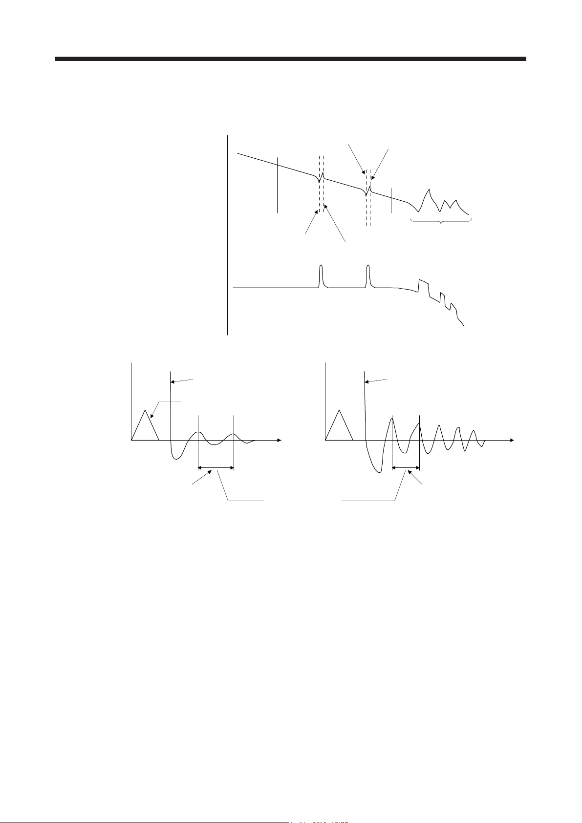
a) When a vibration peak can be confirmed with machine analyzer using MR Configurator2, or
external equipment.
1 Hz
Gain characteristics
Phase
-90 degrees
300 Hz
Vibration suppression control 1 -
Vibration frequency
(anti-resonance frequency)
[Pr. PB19]
Vibration suppression control 1 -
Resonance frequency
[Pr. PB20]
Vibration suppression control 2 -
Vibration frequency
(anti-resonance frequency)
[Pr. PX04]
Vibration suppression control 2 -
Resonance frequency
[Pr. PX05]
Resonance of more than
300 Hz is not the target of control.
b) When vibration can be confirmed using monitor signal or external sensor
t
Motor-side vibration
(droop pulses)
Position command frequency
t
External acceleration pickup signal, etc.
Vibration suppression control -
Vibration frequency
Vibration suppression control -
Resonance frequency
Set the same value.
Vibration cycle [Hz] Vibration cycle [Hz]
Step 3. Fine-adjust "Vibration suppression control - Vibration frequency damping" and "Vibration
suppression control - Resonance frequency damping".
(6) Gain switching function
You can switch gains with the function. You can switch gains during rotation and during stop, and can
use a control command from a controller to switch gains during operation.
(a) Use
The following shows when you use the function.
1) You want to increase the gains during servo-lock but decrease the gains to reduce noise during
rotation.
2) You want to increase the gains during settling to shorten the stop settling time.
3) You want to change the gains using a control command from a controller to ensure stability of the
servo system since the load to motor inertia ratio varies greatly during a stop (e.g. a large load is
mounted on a carrier).
17. APPLICATION OF FUNCTIONS
17 - 49
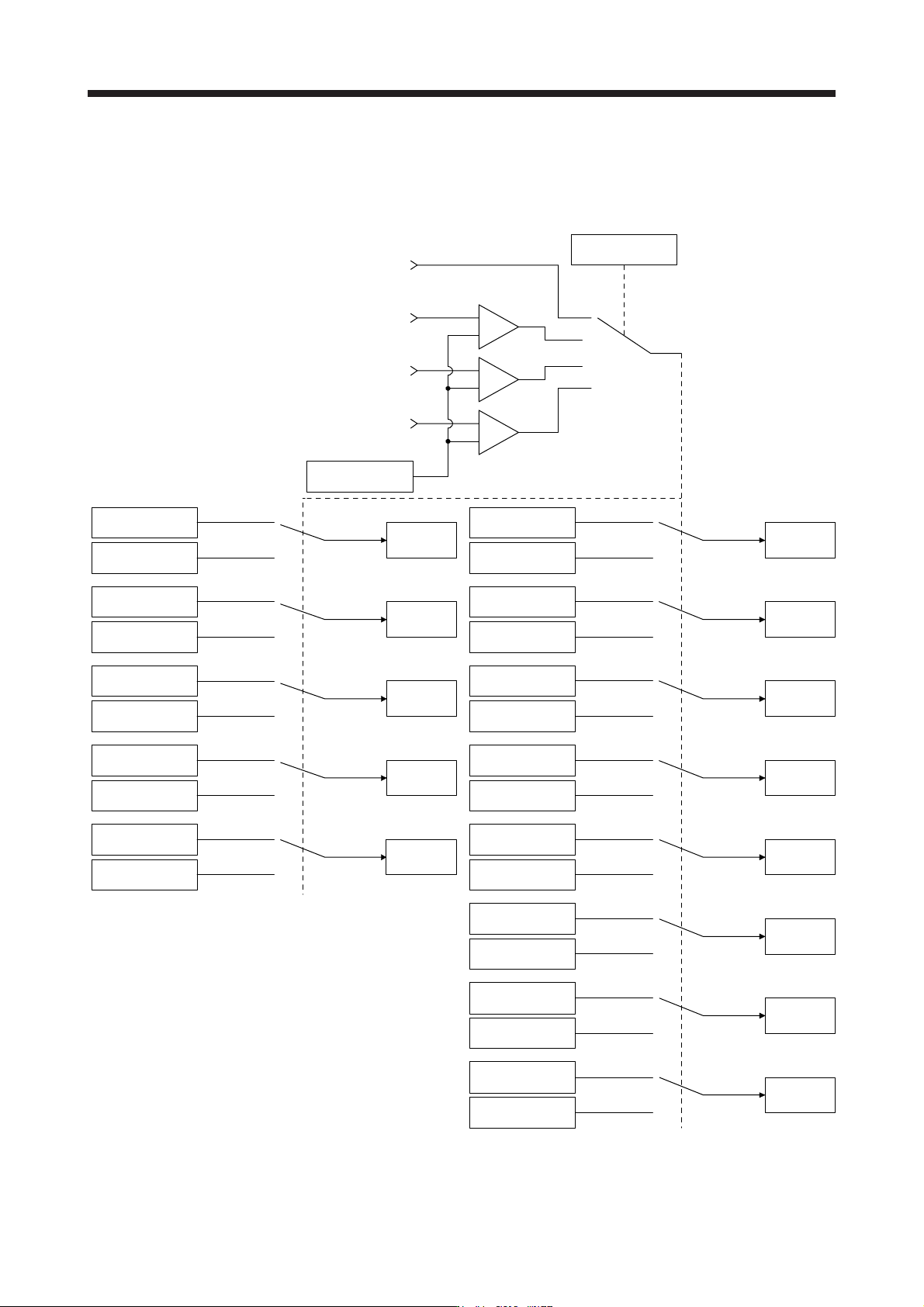
(b) Function block diagram
The control gains, load to motor inertia ratio, and vibration suppression control settings are changed
according to the conditions selected by [Pr. PB26 Gain switching function] and [Pr. PB27 Gain
switching condition].
Command pulse
frequency
+
-
Droop pulses
Model speed
Control command
from controller
Comparator
Changing
CDP
[Pr. PB26]
+
-
+
-
GD2
[Pr. PB06]
GD2B
[Pr. PB29]
Enabled
GD2 value
PG1
[Pr. PB07]
PG1B
[Pr. PX12]
Enabled
PG1 value
PG2
[Pr. PB08]
PG2B
[Pr. PB30]
Enabled
PG2 value
VG2
[Pr. PB09]
VG2B
[Pr. PB31]
Enabled
VG2 value
VIC
[Pr. PB10]
VICB
[Pr. PB32]
Enabled
VIC value
VRF11
[Pr. PB19]
VRF11B
[Pr. PB33]
Enabled
VRF11 value
VRF12
[Pr. PB20]
VRF12B
[Pr. PB34]
Enabled
VRF12 value
CDL
[Pr. PB27]
VRF13
[Pr. PB21]
VRF13B
[Pr. PB35]
Enabled
VRF13 value
VRF14
[Pr. PB22]
VRF14B
[Pr. PB36]
Enabled
VRF14 value
VRF21
[Pr. PX04]
VRF21B
[Pr. PX08]
Enabled
VRF21 value
VRF22
[Pr. PX05]
VRF22B
[Pr. PX09]
Enabled
VRF22 value
VRF23
[Pr. PX06]
VRF23B
[Pr. PX10]
Enabled
VRF23 value
VRF24
[Pr. PX07]
VRF24B
[Pr. PX11]
Enabled
VRF24 value
17. APPLICATION OF FUNCTIONS
17 - 50
(c) Parameter
When using the gain switching function, always select "Manual mode (_ _ _ 3)" of "Gain adjustment
mode selection" in [Pr. PA08 Auto tuning mode]. The gain switching function cannot be used in the
auto tuning mode.
1) Parameter for setting gain switching condition
Parameter Symbol Name Unit Description
PB26 CDP Gain switching function Select a switching condition.
PB27 CDL Gain switching condition [kpulse/s]
/[pulse]
/[r/min]
Set a switching condition values.
PB28 CDT Gain switching time constant [ms] Set the filter time constant for a gain change at switching.
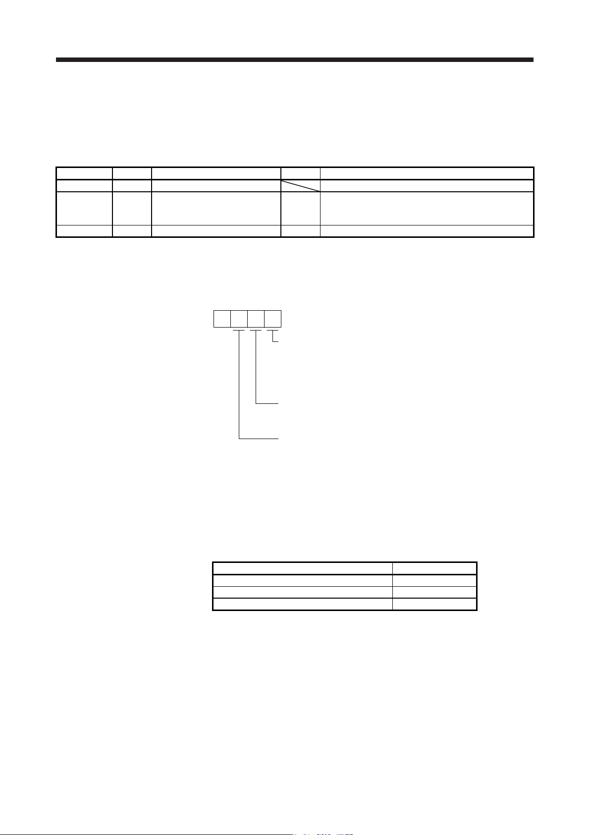
a) [Pr. PB26 Gain switching function]
Used to set the gain switching condition. Select the switching condition in the first to third
digits.
Gain switching selection
0: Disabled
1: Control command from controller is enabled
2: Command frequency
3: Droop pulses
4: Servo motor speed/linear servo motor speed
0
Gain switching condition
0: Gain after switching is enabled with gain switching condition or mor
e
1: Gain after switching is enabled with gain switching condition or less
[Pr. PB26]
Gain switching time constant disabling condition selection
0: Switching time constant enabled
1: Switching time constant disabled
2: Return time constant disabled
b) [Pr. PB27 Gain switching condition]
Set a level to switch gains with [Pr. PB27] after you select "Command frequency", "Droop
pulses", or "Servo motor speed/linear servo motor speed" with the gain switching selection in
[Pr. PB26 Gain switching function].
The setting unit is as follows.
Gain switching condition Unit
Command frequency [kpulse/s]
Droop pulses [pulse]
Servo motor speed/linear servo motor speed [r/min]/[mm/s]
c) [Pr. PB28 Gain switching time constant]
You can set the primary delay filter to each gain at gain switching. This parameter is used to
suppress shock given to the machine if the gain difference is large at gain switching, for
example.