sh030106u.pdf - 第97页
3. SIG NALS A ND WIRI NG 3 - 20 (2) Timing ch art (Note 1) (3 s to 4 s) 95 ms (Note 2) 10 ms 95 ms Servo-on command accepted Main circuit Control circuit Base circuit Servo-on command (from controller) power supply ON OF…
3. SIGNALS AND WIRING
3 - 19
Symbol
Connection target
(application)
Description
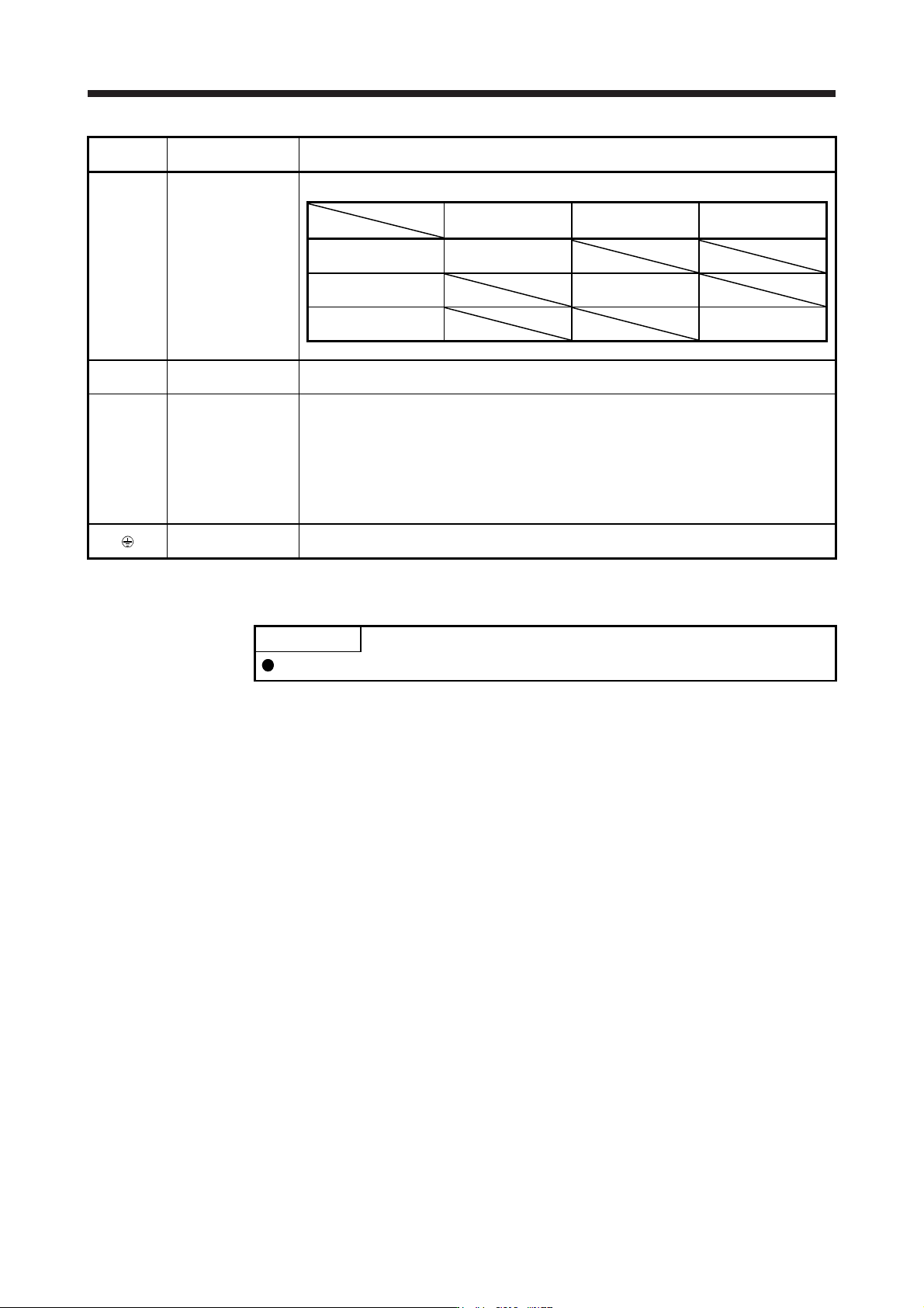
L11/L21
Control circuit power
supply
Supply the following power to L11 and L21.
Servo amplifier
Power
MR-J4-10B(-RJ) to
MR-J4-22KB(-RJ)
MR-J4-60B4(-RJ) to
MR-J4-22KB4(-RJ)
MR-J4-10B1 to
MR-J4-40B1
1-phase 200 V AC to
240 V AC, 50 Hz/60 Hz
L11/L21
1-phase 380 V AC to
480 V AC, 50 Hz/60 Hz
L11/L21
1-phase 100 V AC to
120 V AC, 50 Hz/60 Hz
L11/L21
U/V/W
Servo motor power
input
Connect the servo amplifier power output (U/V/W) to the servo motor power input (U/V/W)
directly. Do not let a magnetic contactor, etc. intervene. Otherwise, it may cause a malfunction.
N-
Power regeneration
converter
Power regeneration
common converter
Brake unit
Multifunction
regeneration
converter
This terminal is used for a power regeneration converter, power regeneration common
converter, brake unit, and multifunction regeneration converter.
For details, refer to sections 11.3 through 11.5 and 11.19.
Protective earth (PE)
Connect it to the grounding terminal of the servo motor and to the protective earth (PE) of the
cabinet for grounding.
3.3.2 Power-on sequence
POINT
The output signal, etc. may be unstable at power-on.
(1) Power-on procedure
1) Always wire the power supply as shown in above section 3.1 using the magnetic contactor with
the main circuit power supply (L1/L2/L3). Configure up an external sequence to switch off the
magnetic contactor as soon as an alarm occurs.
2) Switch on the control circuit power supply (L11/L21) simultaneously with the main circuit power
supply or before switching on the main circuit power supply. If the control circuit power supply is
turned on with the main circuit power supply off, and then the servo-on command is transmitted,
[AL. E9 Main circuit off warning] will occur. Turning on the main circuit power supply stops the
warning and starts the normal operation.
3) The servo amplifier receives the servo-on command within 3 s to 4 s after the main circuit power
supply is switched on.
(Refer to (2) in this section.)
3. SIGNALS AND WIRING
3 - 20
(2) Timing chart
(Note 1)
(3 s to 4 s)
95 ms (Note 2) 10 ms 95 ms
Servo-on command accepted
Main circuit
Control circuit
Base circuit
Servo-on command
(from controller)
power supply
ON
OFF
ON
OFF
ON
OFF
Note 1. This ran
g
e will be "5 s to 6 s" for the linear servo s
y
stem and full
y
closed loop s
y
stem.
2. The time will be lon
g
er durin
g
the ma
g
netic pole detection of a linear servo motor and direct drive motor.
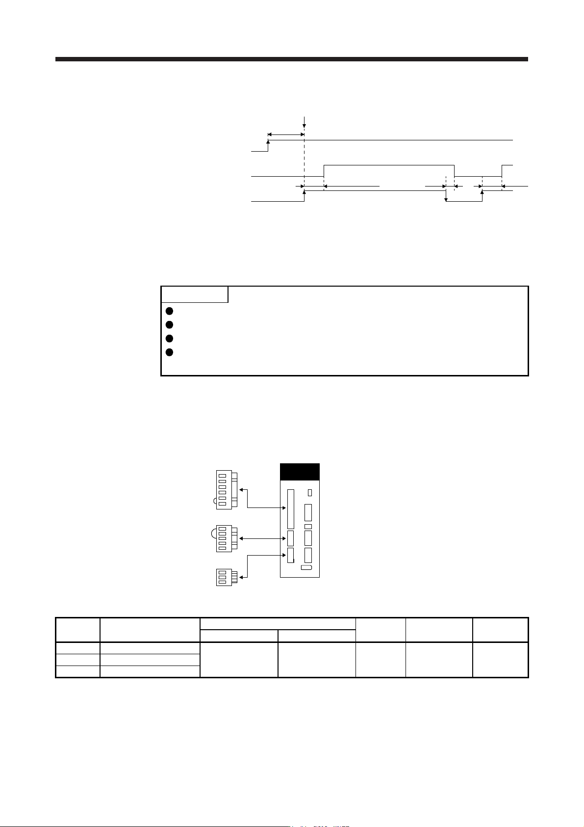
3.3.3 Wiring CNP1, CNP2, and CNP3
POINT
For the wire sizes used for wiring, refer to section 11.9.
When wiring, remove the power connectors from the servo amplifier.
Insert only one wire or ferrule to each wire insertion hole.
MR-J4-500B(-RJ) or more and MR-J4-500B4(-RJ) or more do not have these
connectors.
Use the servo amplifier power connector for wiring CNP1, CNP2, and CNP3.
(1) Connector
(a) MR-J4-10B(-RJ) to MR-J4-100B(-RJ)
CNP2
CNP1
CNP3
Servo amplifier
Table 3.1 Connector and applicable wire
Connector Receptacle assembly
Applicable wire
Stripped
length [mm]
Open tool Manufacturer
Size Insulator OD
CNP1 06JFAT-SAXGDK-H7.5
AWG 18 to 14 3.9 mm or shorter 9
J-FAT-OT (N)
or
J-FAT-OT
JST
CNP2 05JFAT-SAXGDK-H5.0
CNP3 03JFAT-SAXGDK-H7.5
3. SIGNALS AND WIRING
3 - 21
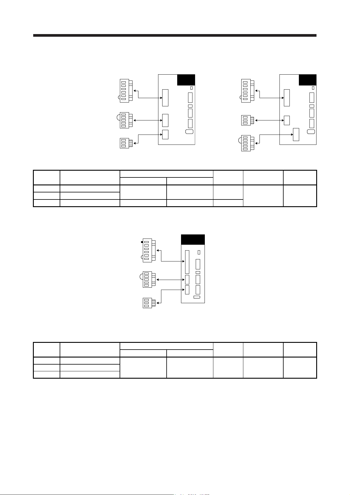
(b) MR-J4-200B(-RJ)/MR-J4-350B(-RJ)
CNP2
CNP1
CNP3
MR-J4-200B(-RJ)
Servo amplifier
CNP3
CNP1
CNP2
MR-J4-350B(-RJ)
Servo amplifier
Table 3.2 Connector and applicable wire
Connector Receptacle assembly
Applicable wire
Stripped
length [mm]
Open tool Manufacturer
Size Insulator OD
CNP1 06JFAT-SAXGFK-XL
AWG 16 to 10 4.7 mm or shorter 11.5
J-FAT-OT-EXL JST
CNP3 03JFAT-SAXGFK-XL
CNP2 05JFAT-SAXGDK-H5.0 AWG 18 to 14 3.9 mm or shorter 9
(c) MR-J4-60B4(-RJ) to MR-J4-350B4(-RJ)
CNP2
CNP1
CNP3
Servo amplifier
(Note)
Note.
A
pin for preventin
g
improper connection is inserted to N- of CNP1 connector.
Table 3.3 Connector and applicable wire
Connector Receptacle assembly
Applicable wire
Stripped
length [mm]
Open tool Manufacturer
Size Insulator OD
CNP1 06JFAT-SAXGDK-HT10.5
AWG 16 to 14 3.9 mm or shorter 10 J-FAT-OT-XL JST
CNP2 05JFAT-SAXGDK-HT7.5
CNP3 03JFAT-SAXGDK-HT10.5