sh030106u.pdf - 第583页
17. APPLICATIO N OF FUNCTIONS 17 - 32 2) Response mode s electio n Select a res ponse mode fr om 3 mod es in the one-t ouc h tuning wi ndow of MR Con figurator2. Table 17. 6 Respons e mod e explana tions Response mode Ex…
17. APPLICATION OF FUNCTIONS
17 - 31
b) Amplifier command method
Input a permissible travel distance. Input it in the load-side resolution unit for the fully closed
loop control mode, and in the servo motor-side resolution unit for other control modes. In the
amplifier command method, the servo motor will be operated in a range between "current
value ± permissible travel distance". Input the permissible travel distance as large as possible
within a range that the movable part does not collide against the machine. Inputting a small
permissible travel distance decreases the possibility that the moving part will collide against
the machine. However, the estimation accuracy of the load to motor inertia ratio may be lower,
resulting in improper tuning.
Also, executing the one-touch tuning in the amplifier command method will generate a
command for the following optimum tuning inside the servo amplifier to start the tuning.
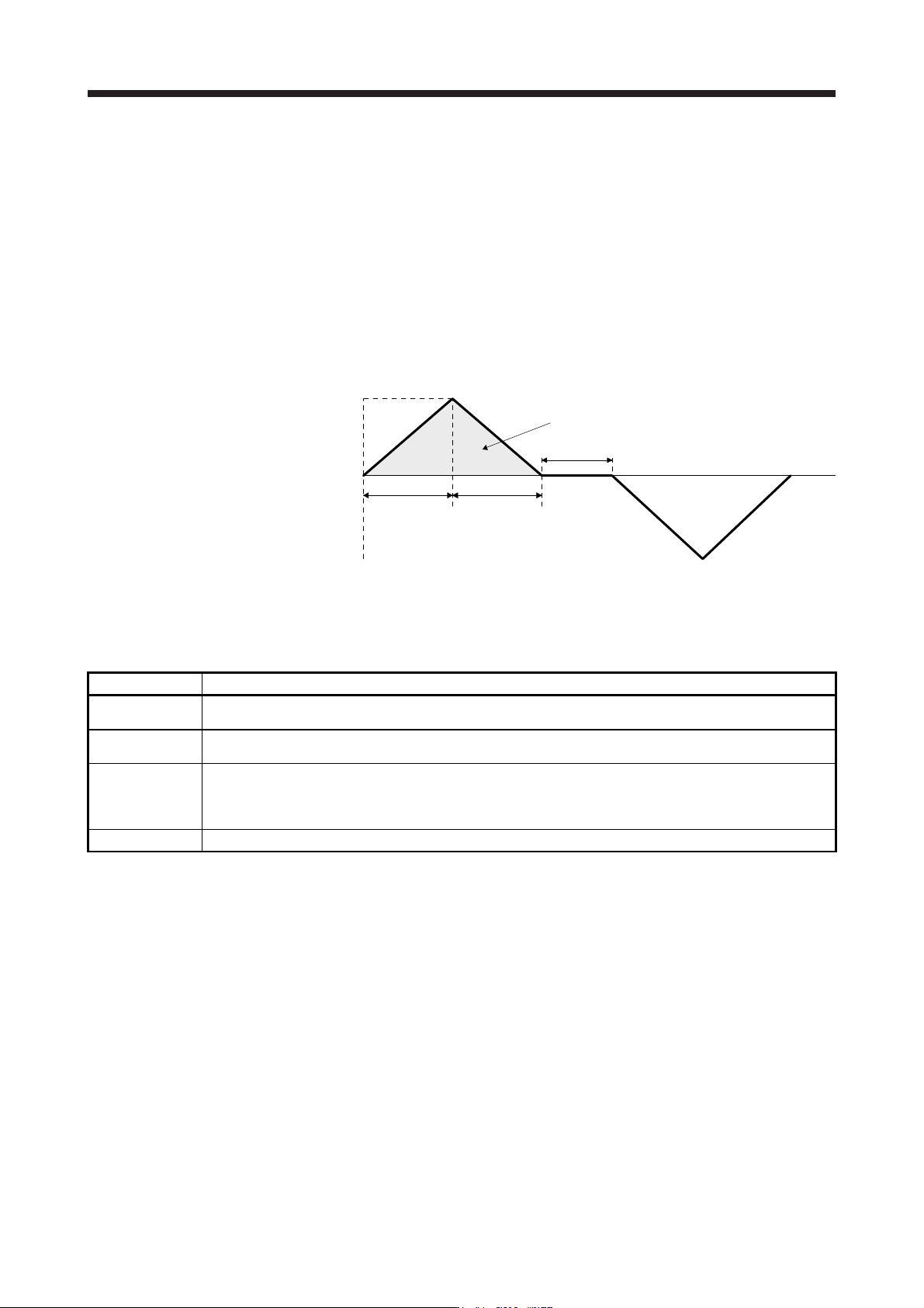
Servo motor
speed
Servo motor
speed (Note)
Forward
rotation
0 r/min
Reverse
rotation
Dwell time (Note)
Deceleration
time constant
(Note)
Travel distance (Note)
Acceleration
time constant
(Note)
Note. It will be automaticall
y
g
enerated in the servo amplifier.
Fig. 17.2 Command generated by one-touch tuning in the amplifier command method
Item Description
Travel distance
An optimum travel distance will be automatically set in the range not exceeding the user-inputted permissible
travel distance with MR Configurator2.
Servo motor speed
A speed not exceeding 1/2 of the rated speed and overspeed alarm detection level ([Pr. PC08]) will be
automatically set.
Acceleration time
constant
Deceleration time
constant
An acceleration time constant/deceleration time constant will be automatically set so as not to exceed 60% of the
rated torque and the torque limit value set at the start of one-touch tuning in the amplifier command method.
Dwell time A dwell time in which the one-touch tuning error "C004" does not occur will be automatically set.
17. APPLICATION OF FUNCTIONS
17 - 32
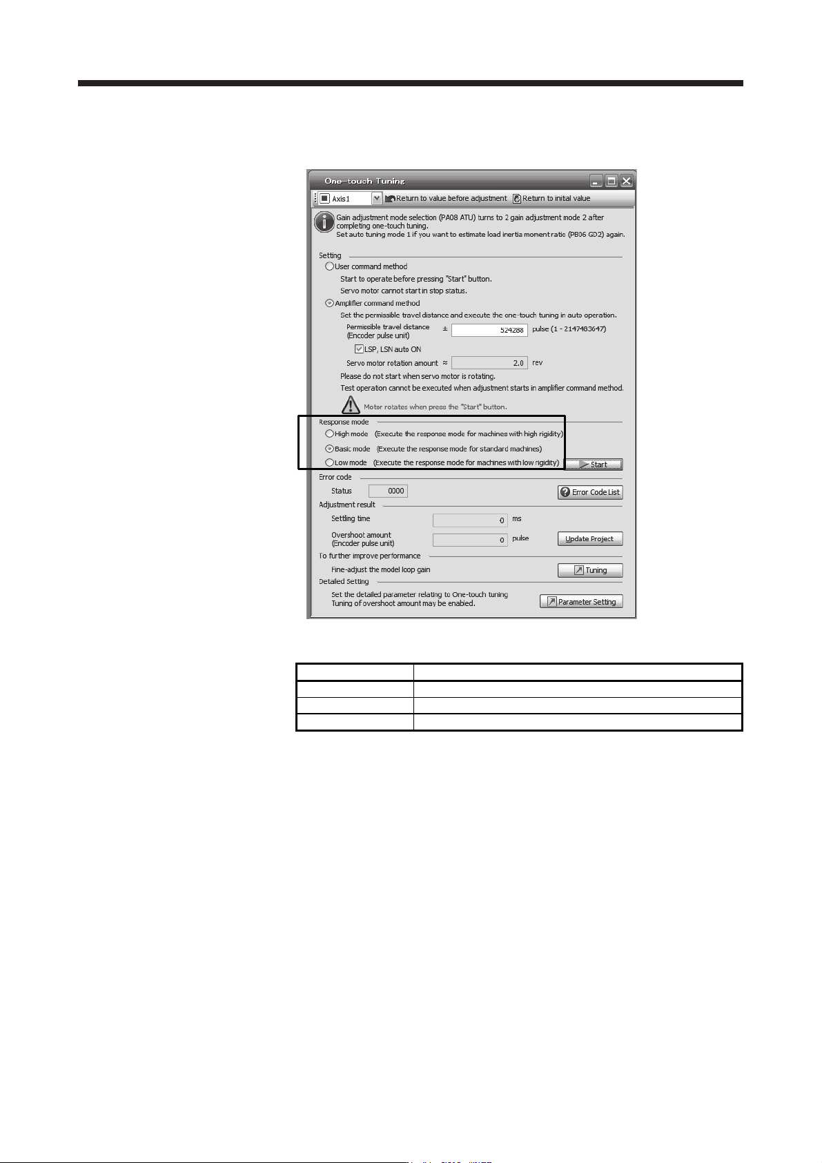
2) Response mode selection
Select a response mode from 3 modes in the one-touch tuning window of MR Configurator2.
Table 17.6 Response mode explanations
Response mode Explanation
High mode This mode is for high-rigid system.
Basic mode This mode is for standard system.
Low mode This mode is for low-rigid system.
17. APPLICATION OF FUNCTIONS
17 - 33
Refer to the following table for selecting a response mode.
Table 17.7 Guideline for response mode
Response mode
Response
Machine characteristic
Low mode Basic mode High mode Guideline of corresponding machine
Low response
General machine
tool conveyor
Arm robot
Precision working
machine
Inserter
Mounter
Bonder
High response
3) One-touch tuning execution
POINT
For equipment in which overshoot during one-touch tuning is in the permissible
level of the in-position range, changing the value of [Pr. PX14 One-touch tuning
overshoot permissible level] will shorten the settling time and improve the
response.
When executing one-touch tuning in the amplifier command method, turn on
EM2. When you turn off EM2 during one-touch tuning, "C008" will be displayed
at status in error code, and the one-touch tuning will be canceled.
When executing the one-touch tuning in the amplifier command method, FLS
(Upper stroke limit) and RLS (Lower stroke limit) will be disabled. Thus, set a
permissible travel distance within a range where moving part collision never
occurs, or execute the one-touch tuning in a state in which the servo motor can
immediately stop in emergency.
When one-touch tuning is executed in the amplifier command method while
magnetic pole detection is not being performed, magnetic pole detection will be
performed, and then one-touch tuning will start after the magnetic pole detection
is completed.