sh030106u.pdf - 第40页
1. FUNCTI ONS AND C ONFIGURATI ON 1 - 23 1.6 Mode l desig nation (1) Rating p late The foll owing sho ws an ex ample of rating plate for expla nation of each i tem. Country of origin Model Capacity Applicable power suppl…
1. FUNCTIONS AND CONFIGURATION
1 - 22
Function Description
Detailed
explanation
Direct drive servo system Direct drive servo system can be configured to drive a direct drive motor. Chapter 15
Fully closed loop system
Fully closed loop system can be configured using the load-side encoder.
This is used with servo amplifiers with software version A3 or later.
Chapter 16
One-touch tuning
Gain adjustment is performed just by one click on a certain button on MR
Configurator2.
MR Configurator2 is necessary for this function.
Section 6.2
SEMI-F47 function (Note)
Enables to avoid triggering [AL. 10 Undervoltage] using the electrical energy charged
in the capacitor in case that an instantaneous power failure occurs during operation.
Use a 3-phase for the input power supply of the servo amplifier. Using a 1-phase 100
V AC/200 V AC for the input power supply will not comply with SEMI-F47 standard.
[Pr. PA20]
[Pr. PF25]
Section 7.4
Tough drive function
This function makes the equipment continue operating even under the condition that
an alarm occurs.
The tough drive function includes two types: the vibration tough drive and the
instantaneous power failure tough drive.
Section 7.3
Drive recorder function
This function continuously monitors the servo status and records the status transition
before and after an alarm for a fixed period of time. You can check the recorded data
on the drive recorder window on MR Configurator2 by clicking the "Graph" button.
However, the drive recorder will not operate on the following conditions.
1. You are using the graph function of MR Configurator2.
2. You are using the machine analyzer function.
3. [Pr. PF21] is set to "-1".
4. The controller is not connected (except the test operation mode).
5. An alarm related to the controller is occurring.
[Pr. PA23]
STO function
This function is a functional safety that complies with IEC/EN 61800-5-2. You can
create a safety system for the equipment easily.
Servo amplifier life diagnosis
function
You can check the cumulative energization time and the number of on/off times of the
inrush relay. This function gives an indication of the replacement time for parts of the
servo amplifier including a capacitor and a relay before they malfunction.
MR Configurator2 is necessary for this function.
Power monitoring function
This function calculates the power running energy and the regenerative power from
the data in the servo amplifier such as speed and current. For the SSCNET III/H
system, MR Configurator2 can display the data, including the power consumption.
Since the servo amplifier can send the data to a servo system controller, you can
analyze the data and display the data on a display.
Machine diagnosis function
From the data in the servo amplifier, this function estimates the friction and vibrational
component of the drive system in the equipment and recognizes an error in the
machine parts, including a ball screw and bearing.
MR Configurator2 is necessary for this function.
Master-slave operation
function
The function transmits a master axis torque to slave axes using driver communication
and the torque as a command drives slave axes by torque control.
This is used with servo amplifiers with software version A8 or later.
Section 17.2
Scale measurement function
The function transmits position information of a scale measurement encoder to the
controller by connecting the scale measurement encoder in semi closed loop control.
This is used with servo amplifiers with software version A8 or later.
Section 17.3
J3 compatibility mode
This amplifier has "J3 compatibility mode" which compatible with the previous MR-J3-
B series. Refer to section 17.1 for software versions.
Section 17.1
Continuous operation to
torque control mode
This enables to smoothly switch the mode from position control mode/speed control
mode to torque control mode without stopping. This also enables to decrease load to
the machine and high quality molding without rapid changes in speed or torque. For
details of the continuous operation to torque control mode, refer to the manuals for
servo system controllers.
[Pr. PB03]
[Pr. PB09]
Refer to the
servo system
controller
manual used.
Lost motion compensation
function
This function improves the response delay occurred when the machine moving
direction is reversed. This is used with servo amplifiers with software version B4 or
later.
Section 7.6
Super trace control
This function sets constant and uniform acceleration/deceleration droop pulses to
almost 0. This is used with servo amplifiers with software version B4 or later.
Section 7.7
Note. For servo s
y
stem controllers which are available with this, contact
y
our local sales office.
1. FUNCTIONS AND CONFIGURATION
1 - 23
1.6 Model designation
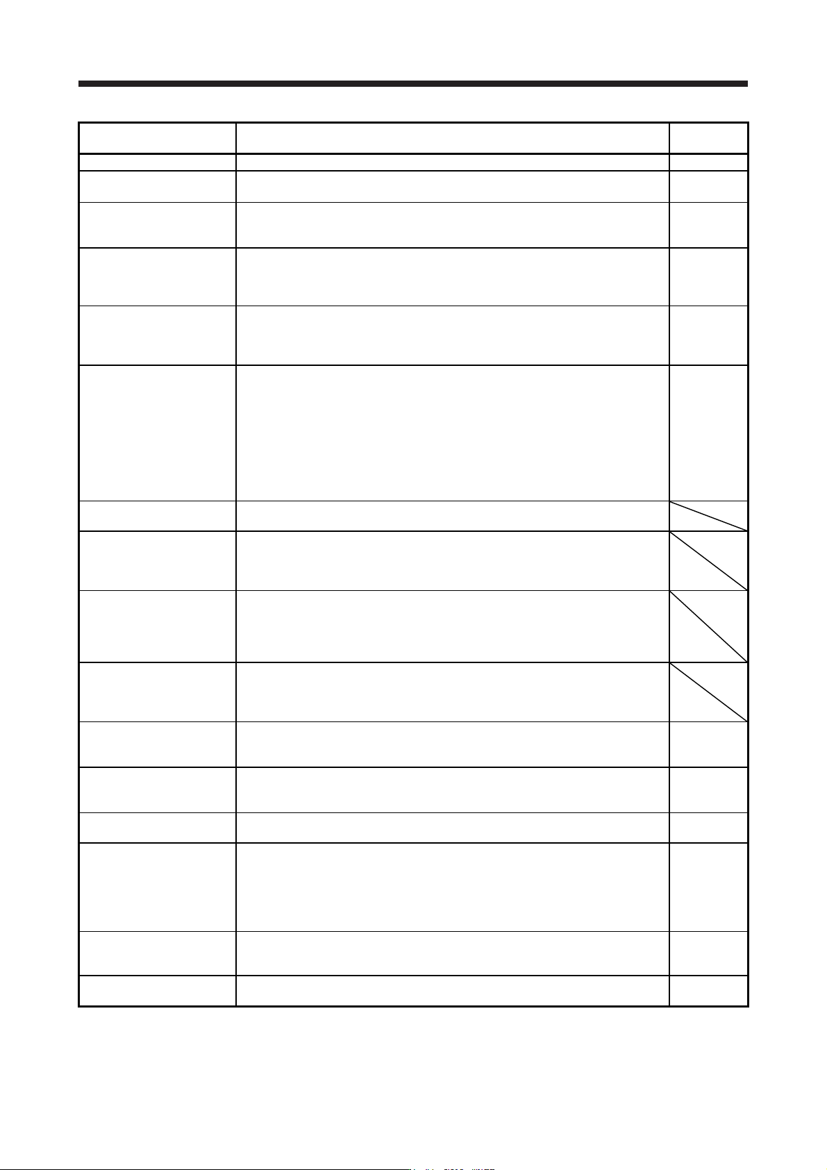
(1) Rating plate
The following shows an example of rating plate for explanation of each item.
Country of origin
Model
Capacity
Applicable power supply
Rated output current
Standard, Manual number
Ambient temperature
IP rating
KC number, The year and month of manufacture manufacture
Serial number
TOKYO 100-8310, JAPAN MADE IN JAPAN
IP20
KCC-REI-MEK-TC300A624G51
Max. Surrounding Air Temp.: 55°C
POWER :100W
MR-J4-10B
AC SERVO
SER.A45001001
OUTPUT: 3PH170V 0-360Hz 1.1A
MAN.: IB(NA)0300175
INPUT : 3AC/AC200-240V 0.9A/1.5A 50/60Hz
STD.: IEC/EN 61800-5-1
DATE:2014-05
MODEL
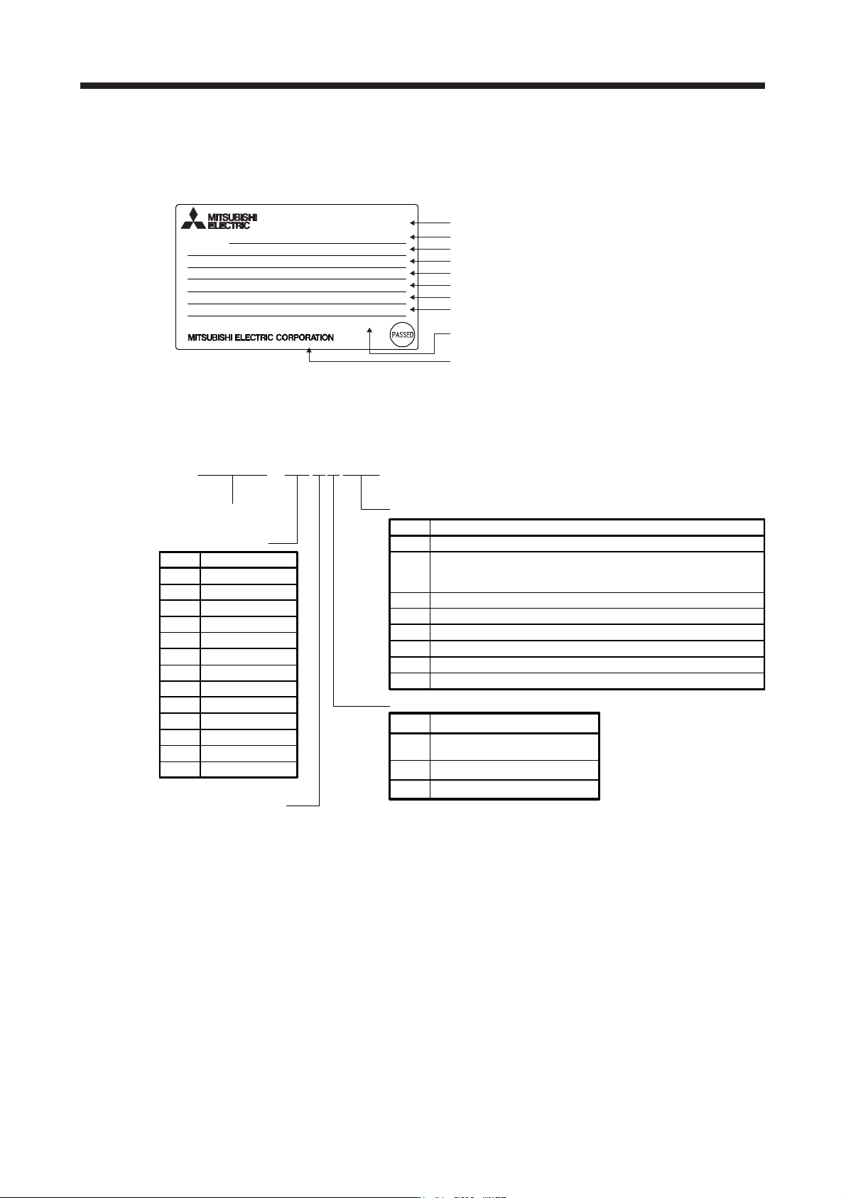
(2) Model
The following describes what each block of a model name indicates. Not all combinations of the symbols
are available.
MR - J 4 - 6 0 B 4 - RJ
Series
Rated output
SSCNETIII/H interface
Special specifications
Symbol Rated output [kW]
10 0.1
20 0.2
40 0.4
Symbol Special specifications
None Standard
MR-J4-_B_ without regenerative resistor (Note 1)
MR-J4-_B_-RJ without regenerative resistor (Note 1)
MR-J4-_B_ with a special coating specification (3C2) (Note 3)
MR-J4-_B_-RJ with a special coating specification (3C2) (Note 3)
-RJ
Fully closed loop control four-wire type/load-side encoder
A/B/Z-phase input compatible/Compatible with MR-D30
functional safety unit
60 0.6
70 0.75
100 1
200 2
350 3.5
500 5
700 7
11K 11
15K 15
22K 22
-PX
-RZ
-EB
-KS
Power supply
Symbol Power supply
None
3-phase or 1-phase
200 V AC to 240 V AC
4
3-phase 380 V AC to 480 V AC
1
1-phase 100 V AC to 120 V AC
MR-J4-_B_ without a dynamic brake (Note 2)
MR-J4-_B_-RJ without a dynamic brake (Note 2)
-ED
-RU
Note 1. Indicates a servo amplifier of 11 kW to 22 kW that does not use a regenerative resistor as standard accessory.
Refer to app. 11.2 for details.
2. D
y
namic brake which is built in 7
k
W or smaller servo amplifiers is removed. Refer to app. 11.1 for details.
3. Type with a specially-coated servo amplifier board (IEC 60721-3-3:1994 Class 3C2). Refer to app. 11.3 for
details.
1. FUNCTIONS AND CONFIGURATION
1 - 24
1.7 Structure
1.7.1 Parts identification
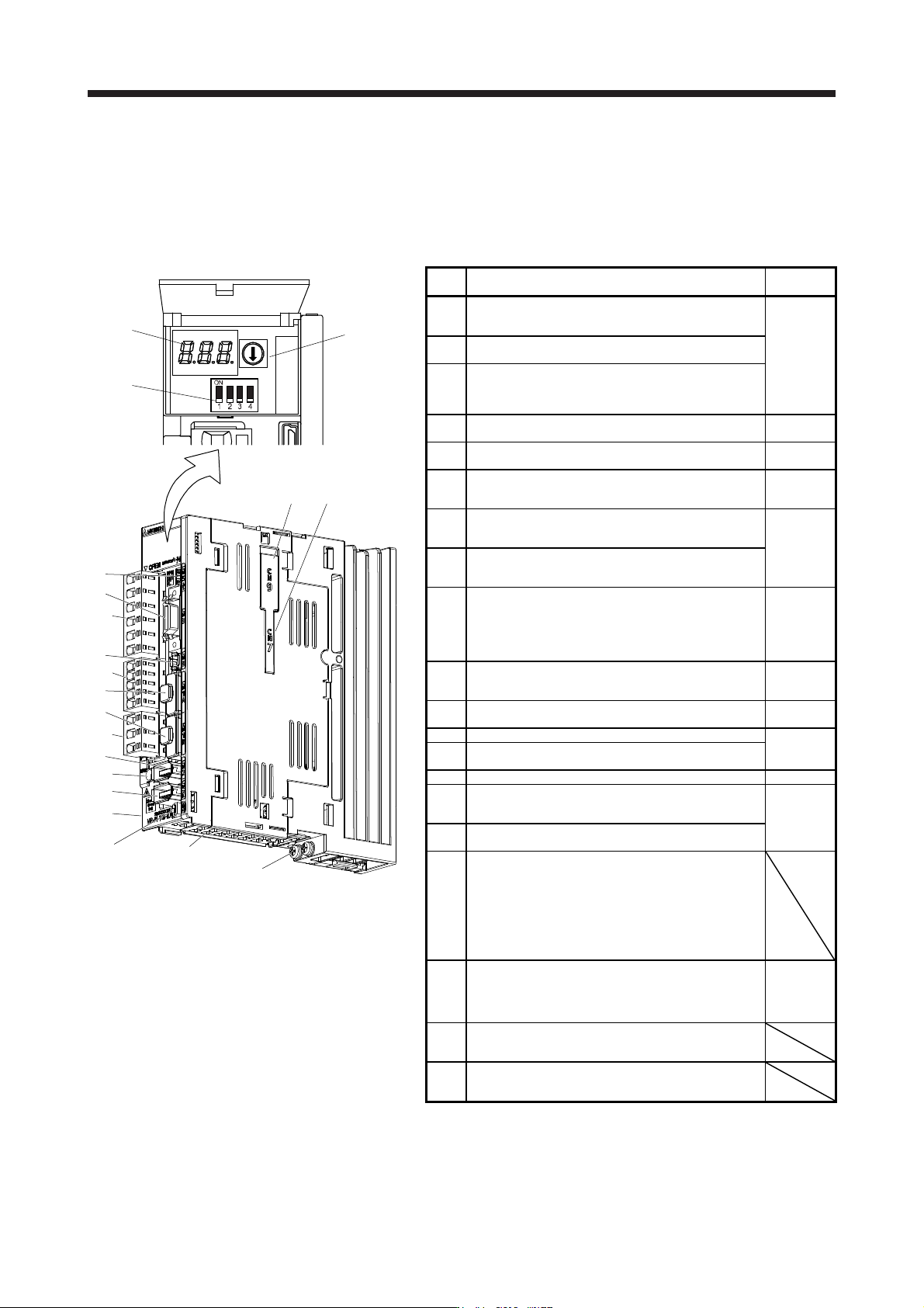
(1) 200 V class
(a) MR-J4-200B(-RJ) or less
The diagram is for MR-J4-10B-RJ.
(1)
(3)
(2)
Inside of the display cover
(5)
(18)
(13)
(10)
(17)
(9)
(6)
(7)
(11)
Bottom
(16)
(15)
(8)
(4)
(14)
Side
(12)
(19)(20)
No. Name/Application
Detailed
explanation
(1)
Display
The 3-digit, 7-segment LED shows the servo status
and the alarm number.
Section 4.3
(2)
Axis selection rotary switch (SW1)
Used to set the axis No. of servo amplifier.
(3)
Control axis setting switch (SW2)
The test operation switch, the disabling control axis
switch, and the auxiliary axis number setting switch
are available.
(4)
USB communication connector (CN5)
Connect with the personal computer.
Section
11.7
(5)
I/O signal connector (CN3)
Used to connect digital I/O signals.
Section 3.2
Section 3.4
(6)
STO input signal connector (CN8)
Used to connect MR-J3-D05 safety logic unit and
external safety relay.
Chapter 13
App. 5
(7)
SSCNET III cable connector (CN1A)
Used to connect the servo system controller or the
previous axis servo amplifier.
Section 3.2
Section 3.4
(8)
SSCNET III cable connector (CN1B)
Used to connect the next axis servo amplifier. For
the final axis, put a cap.
(9)
(Note
2)
Encoder connector (CN2)
Used to connect the servo motor encoder.
Used to connect the servo motor encoder or
external encoder. Refer to table 1.1 for the
compatible external encoders.
Section 3.4
"Servo
Motor
Instruction
Manual
(Vol. 3)"
(10)
Battery connector (CN4)
Used to connect the battery for absolute position
data backup.
Chapter 12
(11)
Battery holde
r
Install the battery for absolute position data backup.
Section
12.2
(12) Protective earth (PE) terminal
Section 3.1
Section 3.3
(13)
Main circuit power connector (CNP1)
Connect the input power supply.
(14) Rating plate Section 1.6
(15)
Control circuit power connector (CNP2)
Connect the control circuit power supply and
regenerative option.
Section 3.1
Section 3.3
(16)
Servo motor power output connector (CNP3)
Connect the servo motor.
(17)
Charge lamp
When the main circuit is charged, this will light.
While this lamp is lit, do not reconnect the cables.
The lamp may light up when only the control circuit
is powered on. Before wiring or inspection, turn off
the main circuit power and the control circuit power,
and wait for 15 minutes or more until the charge
lamp turns off. Then, check the voltage between P+
and N- using the tester, etc.
(18)
(Note
1, 2)
External encoder connector (CN2L)
Refer to table 1.1 for connections of external
encoders.
Section 3.4
"Linear
Encoder
Instruction
Manual"
(19)
Optional unit connector 1 (CN7)
This is for connecting the optional unit. This
connector is attached only on MR-J4-_B_-RJ.
(20)
Optional unit connector 2 (CN9)
This is for connecting the optional unit. This
connector is attached only on MR-J4-_B_-RJ.
Note 1. This is for MR-J4-_B-RJ servo amplifier. MR-J4-_B servo
amplifier does not have CN2L connector.
2. "External encoder" is a term for linear encoder used in the linear
servo system, load-side encoder used in the fully closed loop
system, and scale measurement encoder used with the scale
measurement function in this manual.