sh030106u.pdf - 第676页
APPENDIX App. - 45 App. 13 Optional dat a monitor function The o ptional data moni tor fun ction i s used to m onitor da ta in the servo ampl ifie r with the se rvo system controller. I n the op tiona l data mon itor fun…
APPENDIX
App. - 44
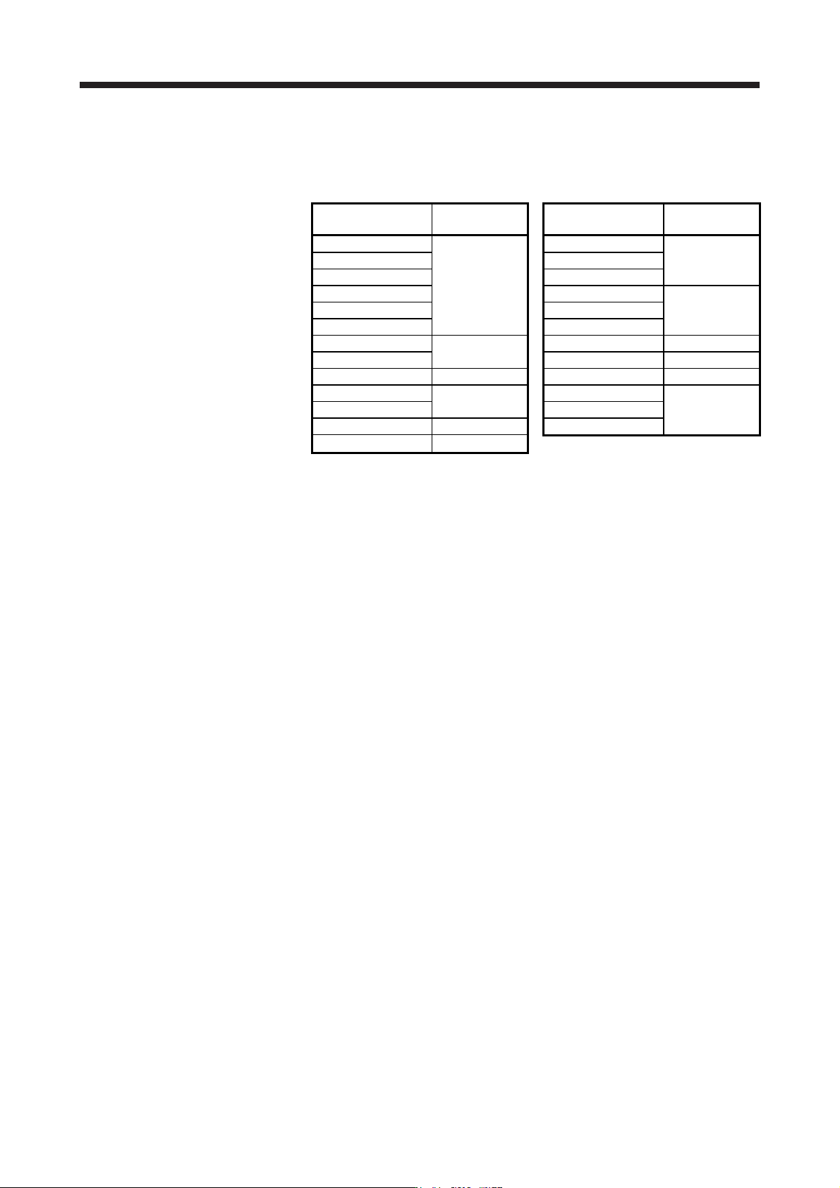
App. 12.2 Magnetic contactor
Use the magnetic contactor with an operation delay time (interval between current being applied to the coil
until closure of contacts) of 80 ms or less (160 ms or less for 5 kW or more).
Servo amplifier
Magnetic
contactor
Servo amplifier
Magnetic
contactor
MR-J4-10B(-RJ) MR-J4-60B4(-RJ)
MR-J4-20B(-RJ) MR-J4-100B4(-RJ) SD-N11
MR-J4-40B(-RJ)
SD-N11
MR-J4-200B4(-RJ)
MR-J4-60B(-RJ) MR-J4-350B4(-RJ)
MR-J4-70B(-RJ) MR-J4-500B4(-RJ) SD-N21
MR-J4-100B(-RJ) MR-J4-700B4(-RJ)
MR-J4-200B(-RJ)
SD-N21
MR-J4-11KB4(-RJ) SD-N25
MR-J4-350B(-RJ) MR-J4-15KB4(-RJ) SD-N35
MR-J4-500B(-RJ) SD-N35 MR-J4-22KB4(-RJ) SD-N50
MR-J4-700B(-RJ)
SD-N50
MR-J4-10B1(-RJ)
MR-J4-11KB(-RJ) MR-J4-20B1(-RJ) SD-N11
MR-J4-15KB(-RJ) SD-N65 MR-J4-40B1(-RJ)
MR-J4-22KB(-RJ) SD-N95

APPENDIX
App. - 45
App. 13 Optional data monitor function
The optional data monitor function is used to monitor data in the servo amplifier with the servo system
controller. In the optional data monitor function, data types of registered monitor and transient command can
be set.
For details of usage, the unit of data types, and others, refer to the manuals for servo system controllers.
App. 13.1 Registered monitor
Data type Description
Effective load ratio The continuous effective load current is displayed.
The effective value is displayed considering a rated current as 100%.
Regenerative load ratio The ratio of regenerative power to permissible regenerative power is displayed in %.
Peak load ratio The maximum torque generated is displayed.
The highest value in the past 15 s is displayed, with the rated torque being 100%.
Position feedback Feedback pulses from the servo motor encoder are counted and displayed.
The "-" symbol is indicated for reverse.
In the fully closed loop control mode, the position within one-revolution is displayed in the
load-side encoder unit after gear.
When the mode is switched to the semi closed loop control mode after the fully closed loop
selection command is turned off, the value in the motor-side encoder unit is displayed.
The displayed range is from -2147483648 pulses to 2147483647 pulses.
Encoder position within one revolution The position in servo motor-side 1-revolution is displayed in the encoder pulse unit.
When the value exceeds the maximum number of pulses, it resets to 0.
Encoder multiple revolution counter
The rotation amount of the servo motor is displayed. The value is counted up by one per
servo motor revolution.
Load inertia moment ratio
The set ratio of the load inertia moment to the servo motor shaft inertia moment is
displayed.
Load to motor mass ratio The load to mass of the linear servo motor primary-side ratio is displayed.
Model loop gain The model loop gain value is displayed.
Main circuit bus voltage The voltage of main circuit converter (between P+ and N-) is displayed.
Cumulative current value The cumulative current value of the servo motor is displayed.
Servo motor speed The servo motor speed is displayed.
Servo motor speed The linear servo motor speed is displayed at linear servo motor driving.
Selected droop pulse The droop pulse set in [Pr. PE10] is displayed.
Module power consumption The module power consumption is displayed.
The positive value is displayed in power running. The negative value is displayed in
regeneration.
Module integral power consumption The module integral power consumption is displayed.
Instantaneous torque The instantaneous torque is displayed.
The value of torque being occurred is displayed in real time considering a rated torque as
100%.
Instantaneous thrust The instantaneous thrust is displayed at linear servo motor driving.
The value of thrust being occurred is displayed in real time considering a continuous thrust
as 100%.
Load-side encoder information 1 (Note)
The item to be displayed depends on the encoder being connected to the load side as
follows.
For a rotary servo motor (HG-KR, HG-MR) or synchronous encoder (Q171ENC-W8), the
cycle counter is displayed.
For an absolute position linear encoder, the absolute position data is displayed.
For an incremental linear encoder, the Z-phase counter (distance from the linear encoder
home position (reference mark)) (32-bit data) is displayed after the Z-phase is passed. The
value before the Z-phase is passed is undefined.
For an A/B/Z-phase differential output linear encoder, the Z-phase counter (distance from
the linear encoder home position (Z-phase)) (16-bit data) is displayed after the Z-phase is
passed. Before the Z-phase is passed, the free-run counter is displayed (the position at
power-on is 0).
For an A/B/Z-phase differential output rotary encoder, the Z-phase counter (distance from
the encoder home position (Z-phase)) (16-bit data) is displayed after the Z-phase is
passed. Before the Z-phase is passed, the free-run counter is displayed (the position at
power-on is 0).

APPENDIX
App. - 46
Data type Description
Load-side encoder information 2 (Note)
The item to be displayed depends on the encoder being connected to the load side as
follows.
For an encoder of a rotary servo motor (HG-KR, HG-MR) or synchronous encoder
(Q171ENC-W8), the multi-revolution ABS counter is displayed.
For an absolute position linear encoder, "0" is displayed.
For an incremental linear encoder, "0" is displayed.
For an A/B/Z-phase differential output linear encoder, "0" is displayed.
For an A/B/Z-phase differential output rotary encoder, "0" is displayed.
Scale free-run counter The free-run counter of the load-side encoder is displayed (the position at power-on is 0).
Z-phase counter The Z-phase counter is displayed in the encoder pulse unit.
For an incremental type linear encoder, the Z-phase counter is displayed. The value is
counted up from 0 based on the home position (reference mark).
For an absolute position type linear encoder, the encoder absolute position is displayed.
Servo motor thermistor temperature The thermistor temperature is displayed for the servo motor with a thermistor.
For the servo motor without thermistor, "9999" is displayed.
For the servo motor with a thermistor, refer to each servo motor instruction manual.
Disturbance torque
The difference between the torque necessary to drive the servo motor and the actually
required torque (Torque current value) is displayed as the disturbance torque.
Disturbance thrust
The difference between the thrust necessary to drive the linear servo motor and the
actually required thrust (Thrust current value) is displayed as the disturbance thrust.
Overload alarm margin
The margins to the levels which trigger [AL. 50 Overload 1] and [AL. 51 Overload 2] are
displayed in percentage.
Error excessive alarm margin
The margin to the level which triggers the error excessive alarm is displayed in units of
encoder pulses.
The error excessive alarm occurs at 0 pulses.
Settling time
The time (Settling time) after command is completed until INP (In-position) turns on is
displayed.
Overshoot amount The overshoot amount during position control is displayed in units of encoder pulses.
Servo motor side/load-side position
deviation
During fully closed loop control, a deviation between servo motor side position and load-
side position is displayed.
The number of pulses displayed is in the load-side encoder pulse unit.
When the mode is switched to the semi closed loop control mode after the fully closed loop
selection command is turned off, "0" is displayed.
The displayed range is from -2147483647 pulses to 2147483647 pulses. It is clamped with
the maximum value.
Servo motor side/load-side speed
deviation
During fully closed loop control, a deviation between servo motor side speed and load-side
speed is displayed.
Internal temperature of encoder
The internal temperature of encoder is displayed. "0" is displayed for the linear servo
motor. When an encoder communication error occurs, the last value will be displayed
before the error.
This is available with servo amplifiers with software version C4 or later.
Servo command value The position command from the controller is displayed.
Torque command The torque command from the controller is displayed.
Note. The contents of "Load-side encoder information 1" and "Load-side encoder information 2" differ from those described in app. 13.2.