sh030106u.pdf - 第609页
17. APPLICATIO N OF FUNCTIONS 17 - 58 The foll owing sho ws the fu nction block diagram of the vibration toug h drive func tio n. The functio n detec ts mach ine reson ance fre quenc y and c ompares i t with [Pr. PB1 3] …
17. APPLICATION OF FUNCTIONS
17 - 57
(7) Tough drive function
POINT
Set enable/disable of the tough drive function with [Pr. PX25 Tough drive
setting]. (Refer to (2) in this section.)
This function makes the equipment continue operating even under the condition that an alarm occurs.
The vibration tough drive function and instantaneous power failure tough drive function are available with
the J3 extension function.
(a) Vibration tough drive function
This function prevents vibration by resetting a filter instantaneously when machine resonance occurs
due to varied vibration frequency caused by machine aging.
To reset the machine resonance suppression filters with the function, [Pr. PB13 Machine resonance
suppression filter 1] and [Pr. PB15 Machine resonance suppression filter 2] should be set in
advance.
Set [Pr. PB13] and [Pr. PB15] as follows.
1) One-touch tuning execution (Refer to (4) in this section.)
2) Manual setting (Refer to (2) in this section.)
The vibration tough drive function operates when a detected machine resonance frequency is within
±30% for a value set in [Pr. PB13 Machine resonance suppression filter 1] or [Pr. PB15 Machine
resonance suppression filter 2].
To set a detection level of the function, set sensitivity in [Pr. PX26 Vibration tough drive - Oscillation
detection level].
POINT
Resetting [Pr. PB13] and [Pr. PB15] by the vibration tough drive function is
performed constantly. However, the number of write times to the EEPROM is
limited to once per hour.
The vibration tough drive function does not reset [Pr. PX17 Machine resonance
suppression filter 3], [Pr. PX19 Machine resonance suppression filter 4], and [Pr.
PX21 Machine resonance suppression filter 5].
The vibration tough drive function does not detect a vibration of 100 Hz or less.
17. APPLICATION OF FUNCTIONS
17 - 58
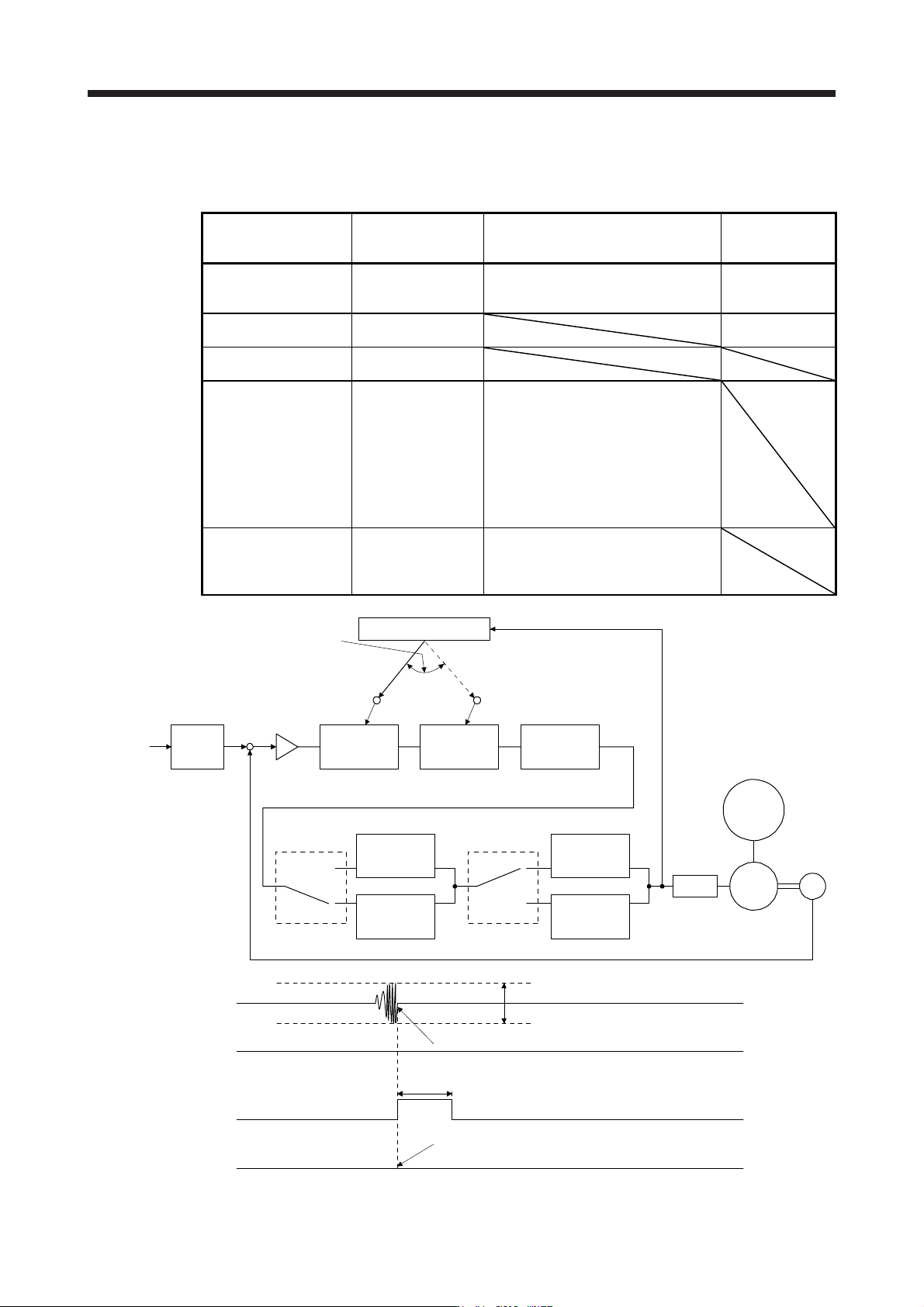
The following shows the function block diagram of the vibration tough drive function.
The function detects machine resonance frequency and compares it with [Pr. PB13] and [Pr. PB15], and
reset a machine resonance frequency of a parameter whose set value is closer.
Filter Setting parameter Precaution
Parameter that is
reset with vibration
tough drive function
Machine resonance
suppression filter 1
PB01/PB13/PB14
The filter can be set automatically with
"Filter tuning mode selection" in [Pr.
PB01].
PB13
Machine resonance
suppression filter 2
PB15/PB16 PB15
Machine resonance
suppression filter 3
PX17/PX18
Machine resonance
suppression filter 4
PX19/PX20 Enabling the machine resonance
suppression filter 4 disables the shaft
resonance suppression filter.
Using the shaft resonance suppression
filter is recommended because it is
adjusted properly depending on the
usage situation.
The shaft resonance suppression filter is
enabled for the initial setting.
Machine resonance
suppression filter 5
PX21/PX22
Enabling the robust filter disables the
machine resonance suppression filter 5.
The robust filter is disabled for the initial
setting.
Command
pulse train
Command
filter
Encoder
Servo motor
PWM
M
Load
+
-
Machine
resonance
suppression
filter 1
[Pr. PB13] [Pr. PB15] [Pr. PX17]
Machine
resonance
suppression
filter 2
Machine
resonance
suppression
filter 3
Machine
resonance
suppression
filter 4
Machine
resonance
suppression
filter 5
Shaft
resonance
suppression
filter
Robust filter
[Pr. PX19]
[Pr. PX21]
[Pr. PB17]
[Pr. PX20] [Pr. PX31]
Updates the parameter
whose setting is the
closest to the machine
resonance frequency.
Vibration tough drive
Torque
ALM
(Malfunction)
WNG
(Warning)
MTTR
(During tough drive)
ON
OFF
[Pr. PX26 Vibration tough drive - Oscillation detection level]
Detects the machine resonance and reconfigures the filter automatically.
During tough drive (MTTR) is not turned on in the vibration tough drive function.
ON
OFF
ON
OFF
5 s
17. APPLICATION OF FUNCTIONS
17 - 59
(b) Instantaneous power failure tough drive function
The instantaneous power failure tough drive function avoids [AL. 10 Undervoltage] even when an
instantaneous power failure occurs during operation. When the instantaneous power failure tough
drive activates, the function will increase the tolerance against instantaneous power failure using the
electrical energy charged in the capacitor in the servo amplifier and will change an alarm level of [AL.
10 Undervoltage] simultaneously. The [AL. 10.1 Voltage drop in the control circuit power] detection
time for the control circuit power supply can be changed by [Pr. PX28 SEMI-F47 function -
Instantaneous power failure detection time]. In addition, [AL. 10.2 Voltage drop in the main circuit
power] detection level for the bus voltage is changed automatically.
POINT
MBR (Electromagnetic brake interlock) will not turn off during the instantaneous
power failure tough drive.
When selecting "Enabled (_ _ _ 1)" for "Torque limit function selection at
instantaneous power failure" in [Pr. PX23], if an instantaneous power failure
occurs during operation, you can save electric energy charged in the capacitor in
the servo amplifier by limiting torque at acceleration. You can also delay the time
until the occurrence of [AL. 10.2 Voltage drop in the main circuit power]. Doing
this will enable you to set a longer time in [Pr. PX28 SEMI-F47 function -
Instantaneous power failure detection time].
When the load of instantaneous power failure is large, [AL. 10.2] caused by the
bus voltage drop may occur regardless of the set value of [Pr. PX28 SEMI-F47
function - Instantaneous power failure detection time].
The external dynamic brake cannot be used for compliance with SEMI-F47
standard. Do not assign DB (Dynamic brake interlock) in [Pr. PD07] to [Pr.
PD09]. Failure to do so will cause the servo amplifier to become servo-off when
an instantaneous power failure occurs.
The setting range of [Pr. PX28 SEMI-F47 function - Instantaneous power failure
detection time] differs depending on the software version of the servo amplifier
as follows.
Software version C0 or later: Setting range 30 ms to 200 ms
Software version C1 or earlier: Setting range 30 ms to 500 ms
To comply with SEMI-F47 standard, it is unnecessary to change the initial value
(200 ms).
When the instantaneous power failure time exceeds 200 ms, and if the
instantaneous power failure voltage is less than 70 % of the rated input voltage,
the power may be turned off normally even if a value larger than 200 ms is set in
the parameter.