sh030106u.pdf - 第615页
17. APPLICATIO N OF FUNCTIONS 17 - 64 (c) Calculation of tolera nce a gainst insta ntaneous power fail ur e Table 17. 10 shows toleranc e ag ainst ins tanta neous po wer failure when i nstantane ous pow er failur e volta…
17. APPLICATION OF FUNCTIONS
17 - 63
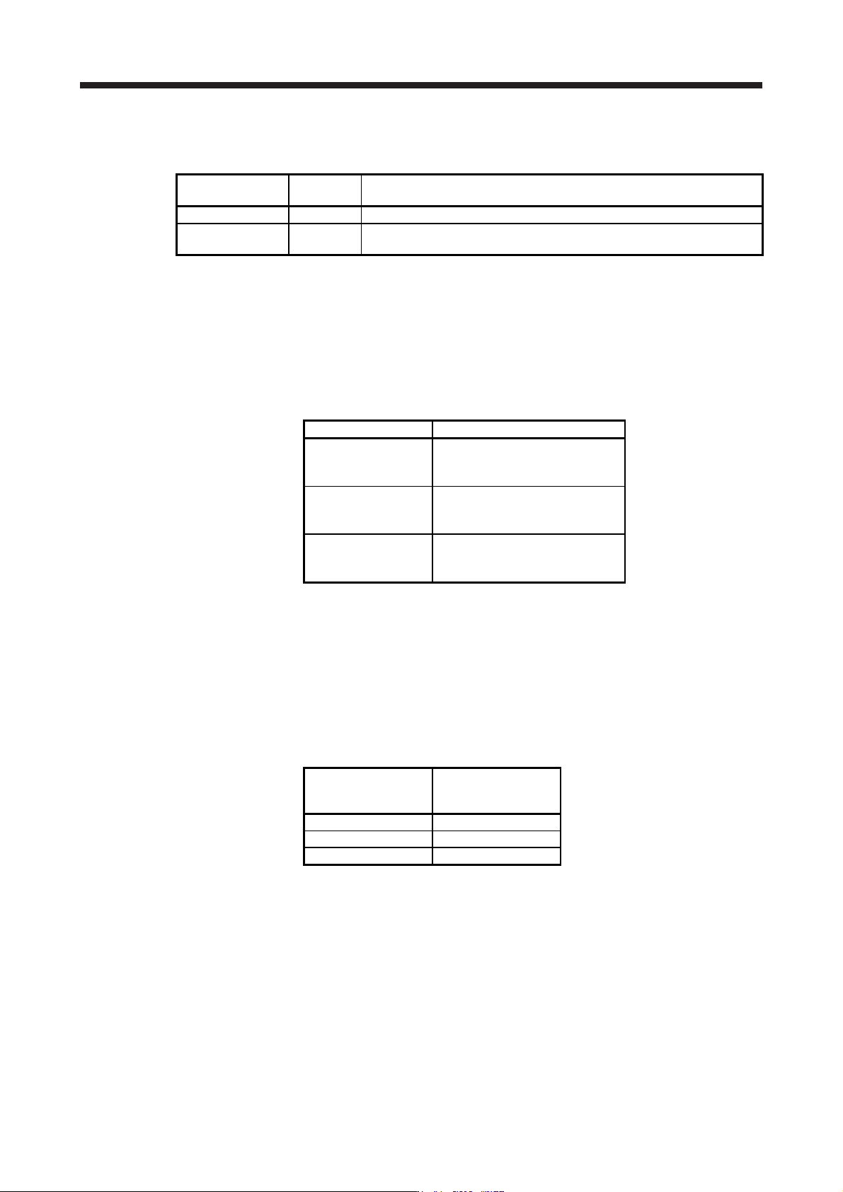
(a) Parameter setting
Setting [Pr. PX25] and [Pr. PX28] as follows will enable SEMI-F47 function.
Parameter
Setting
value
Description
PX25 _ 1 _ _ Enable SEMI-F47 function selection.
PX28 200
Set the time [ms] of the [AL. 10.1 Voltage drop in the control circuit power]
occurrence.
Enabling SEMI-F47 function will change operation as follows.
1) The voltage will drop in the control circuit power with "Rated voltage × 50% or less". 200 ms later,
[AL. 10.1 Voltage drop in the control circuit power] will occur.
2) [AL. 10.2 Voltage drop in the main circuit power] will occur when bus voltage is as follows.
Table 17.8 Voltages which trigger [AL. 10.2 Voltage drop in the main circuit power]
Servo amplifier Bus voltage which triggers alarm
MR-J4-10B(-RJ)
to
MR-J4-700B(-RJ)
158 V DC
MR-J4-11KB(-RJ)
to
MR-J4-22KB(-RJ)
200 V DC
MR-J4-60B4(-RJ)
to
MR-J4-22KB4(-RJ)
380 V DC
3) MBR (Electromagnetic brake interlock) will turn off when [AL. 10.1 Voltage drop in the control
circuit power] occurs.
(b) Requirements conditions of SEMI-F47 standard
Table 17.9 shows the permissible time of instantaneous power failure for instantaneous power failure
of SEMI-F47 standard.
Table 17.9 Requirements conditions of SEMI-F47 standard
Instantaneous power
failure voltage
Permissible time of
instantaneous power
failure [s]
Rated voltage × 80% 1
Rated voltage × 70% 0.5
Rated voltage × 50% 0.2

17. APPLICATION OF FUNCTIONS
17 - 64
(c) Calculation of tolerance against instantaneous power failure
Table 17.10 shows tolerance against instantaneous power failure when instantaneous power failure
voltage is "rated voltage × 50%" and instantaneous power failure time is 200 ms.
Table 17.10 Tolerance against instantaneous power failure
(instantaneous power failure voltage = rated voltage × 50%,
instantaneous power failure time = 200 ms)
Servo amplifier
Instantaneous maximum
output [W]
Tolerance against
instantaneous
power failure [W]
(voltage drop between lines)
MR-J4-10B(-RJ) 350 250
MR-J4-20B(-RJ) 700 420
MR-J4-40B(-RJ) 1400 630
MR-J4-60B(-RJ) 2100 410
MR-J4-70B(-RJ) 2625 1150
MR-J4-100B(-RJ) 3000 1190
MR-J4-200B(-RJ) 5400 2040
MR-J4-350B(-RJ) 10500 2600
MR-J4-500B(-RJ) 15000 4100
MR-J4-700B(-RJ) 21000 5900
MR-J4-11KB(-RJ) 40000 2600
MR-J4-15KB(-RJ) 50000 3500
MR-J4-22KB(-RJ) 56000 4300
MR-J4-60B4(-RJ) 1900 190
MR-J4-100B4(-RJ) 3500 200
MR-J4-200B4(-RJ) 5400 350
MR-J4-350B4(-RJ) 10500 730
MR-J4-500B4(-RJ) 15000 890
MR-J4-700B4(-RJ) 21000 1500
MR-J4-11KB4(-RJ) 40000 2400
MR-J4-15KB4(-RJ) 50000 3200
MR-J4-22KB4(-RJ) 56000 4200
Instantaneous maximum output means power which servo amplifier can output in maximum torque
at rated speed. You can examine margins to compare the values of following conditions and
instantaneous maximum output.
Even if driving at maximum torque with low speed in actual operation, the motor will not drive with
the maximum output. This can be handled as a margin.
The following shows the conditions of tolerance against instantaneous power failure.
1) Delta connection
For the 3-phase (L1/L2/L3) delta connection, an instantaneous power failure occurs in the voltage
between a pair of lines (e.g. between L1 and L2) among voltages between three pairs of lines
(between L1 and L2, L2 and L3, or L3 and L1).
2) Star connection
For the 3-phase (L1/L2/L3/neutral point N) star connection, an instantaneous power failure occurs
in the voltage between a pair of lines (e.g. between L1 and N) among voltages at six locations,
between three pairs of lines (between L1 and L2, L2 and L3, or L3 and L1) and between one of
the lines and the neutral point (between L1 and N, L2 and N, or L3 and N).
17. APPLICATION OF FUNCTIONS
17 - 65
(9) Lost motion compensation function
POINT
The lost motion compensation function is enabled only in the position control
mode.
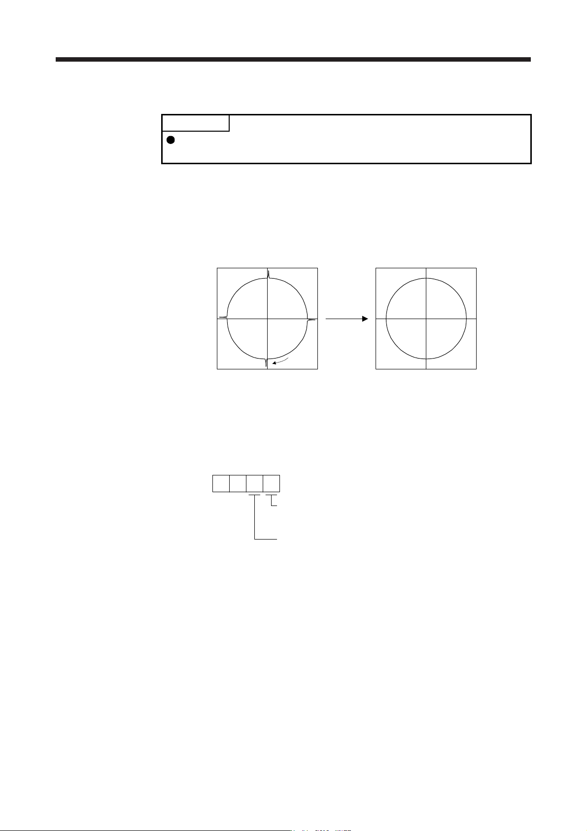
The lost motion compensation function corrects response delays (caused by a non-sensitive band due to
friction, twist, expansion, and backlash) caused when the machine travel direction is reversed. This
function contributes to improvement for protrusions that occur at a quadrant change and streaks that
occur at a quadrant change during circular cutting.
This function is effective when a high follow-up performance is required such as drawing an arc with an
X-Y table.
The locus before compensation The locus after compensation
Compensation
Travel
direction
(a) Parameter setting
Setting [Pr. PX36] to [Pr. PX42] enables the lost motion compensation function.
1) Lost motion compensation function selection ([Pr. PX40])
Select the lost motion compensation function.
Lost motion compensation selection
0: Lost motion compensation disabled
1: Lost motion compensation enabled
0
Unit setting of lost motion compensation non-sensitive band
0: 1 pulse unit
1: 1 kpulse unit
[Pr. PX40]
0
2) Lost motion compensation ([Pr. PX36]/[Pr. PX37])
Set the same value for the lost motion compensation for each of when the forward rotation
switches to the reverse rotation and when the reverse rotation switches to the forward rotation.
When the heights of protrusions differ depending on the travel direction, set the different
compensation for each travel direction. Set a value twice the usual friction torque and adjust the
value while checking protrusions.
3) Torque offset ([Pr. PX39])
For a vertical axis, unbalanced torque occurs due to the gravity. Although setting the torque offset
is usually unnecessary, setting unbalanced torque of a machine as a torque offset cancels the
unbalanced torque. The torque offset does not need to be set for a machine not generating
unbalanced torque. The torque offset cannot be used for linear servo motors and direct drive
motors. Set 0.00%.