sh030106u.pdf - 第307页
10. CHA RACT ERISTI CS 10 - 2 The foll owing tabl e shows c ombinat ions of each s ervo motor and gr aph of ov erloa d protect ion charact eristi cs. Rotary serv o motor Graph of overl oad protecti on charact eristics HG…
10. CHARACTERISTICS
10 - 1
10. CHARACTERISTICS
POINT
For the characteristics of the linear servo motor and the direct drive motor, refer
to sections 14.4 and 15.4.
10.1 Overload protection characteristics
An electronic thermal is built in the servo amplifier to protect the servo motor, servo amplifier and servo
motor power wires from overloads.
[AL. 50 Overload 1] occurs if overload operation performed is above the electronic thermal protection curve
shown in fig. 10.1 [AL. 51 Overload 2] occurs if the maximum current is applied continuously for several
seconds due to machine collision, etc. Use the equipment on the left-hand side area of the continuous or
broken line in the graph.
For the system where the unbalanced torque occurs, such as a vertical axis system, the unbalanced torque
of the machine should be kept at 70% or less of the rated torque.
This servo amplifier has solid-state servo motor overload protection. (The servo motor overload current (full
load current) is set on the basis of 120% rated current of the servo amplifier.)
10. CHARACTERISTICS
10 - 2
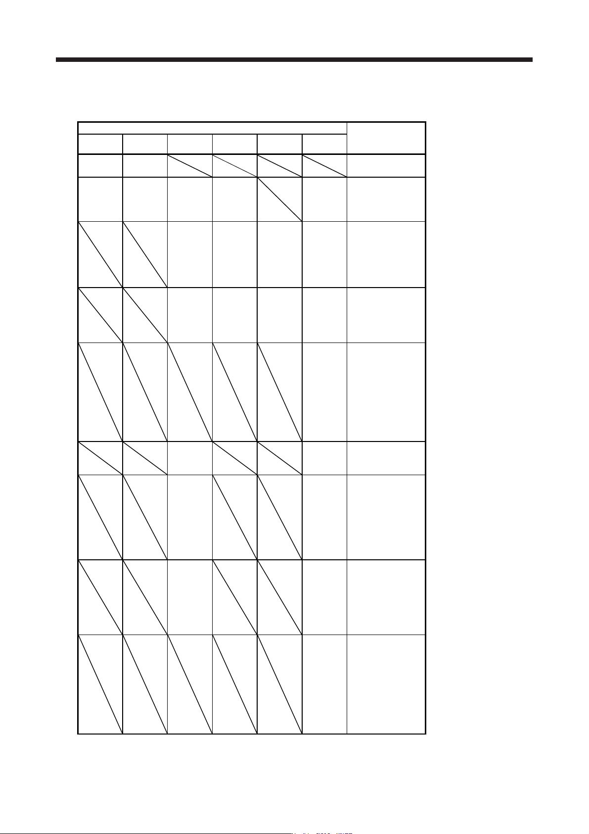
The following table shows combinations of each servo motor and graph of overload protection
characteristics.
Rotary servo motor
Graph of overload
protection
characteristics
HG-KR HG-MR HG-SR HG-UR HG-RR HG-JR
053
13
053
13
Characteristics a
23
43
73
23
43
73
51
81
52
102
72 53 (Note)
73
103
Characteristics b
121
201
152
202
301
352
152
202
103
153
203
73 (Note)
103 (Note)
153 (Note)
203 (Note)
353
Characteristics c
421
502
702
352
502
353
503
353 (Note)
601
701M
503 (Note)
703
Characteristics d
801
12K1
15K1
20K1
25K1
11K1M
15K1M
22K1M
903
Characteristics e
524
1024
534 (Note)
734
1034
Characteristics b
1524
2024
3524
734 (Note)
1034
(Note)
1534
(Note)
2034
(Note)
3534
Characteristics c
5024
7024
3534
(Note)
6014
701M4
5034
(Note)
7034
Characteristics d
8014
12K14
15K14
20K14
25K14
11K1M4
15K1M4
22K1M4
9034
Characteristics e
Note. This combination is for increasin
g
the maximum torque of the servo motor to 400%.
10. CHARACTERISTICS
10 - 3
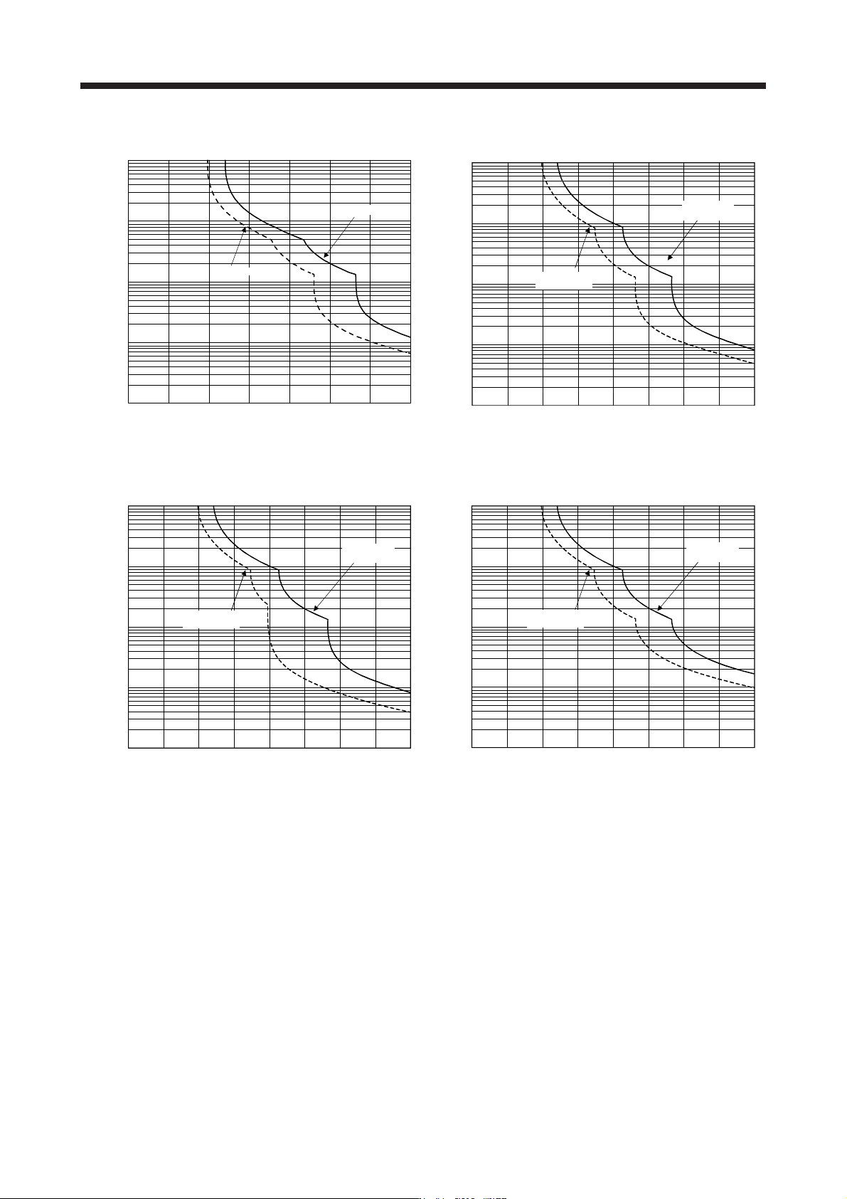
The following graphs show overload protection characteristics.
(Note 1, 2) Load ratio [%]
1000
100
10
1
0.1
100 200 300 350
0
50 150 250
Operating
Servo-lock
Operation time [s]
Characteristics a
1000
100
10
1
0.1
100 200 300 400
0 50 150 250 350
Load ratio [%]
(Note 1, 2, 3)
Servo-lock
Operating
Operation time [s]
Characteristics b
Load ratio [%]
(Note 1, 3)
1000
100
10
1
0.1
100 200 300 400
0
Servo-lock
Operating
Operation time [s]
50 150 250 350
Characteristics c
1000
100
10
1
0.1
100 200 300 400
0 50 150 250 350
Load ratio [%]
(Note 1, 3)
Servo-lock
Operating
Operation time [s]
Characteristics d