sh030106u.pdf - 第455页
13. USIN G STO FUNCTI ON 13 - 2 13. 1.4 Re sidual r isks of the STO function Machine manufact urers ar e res ponsible for a ll ris k eval uations a nd all as sociat ed res idual risk s. Bel ow are resid ual ri sks associ…
13. USING STO FUNCTION
13 - 1
13. USING STO FUNCTION
POINT
In the torque control mode, the forced stop deceleration function is not available.
13.1 Introduction
This section provides the cautions of the STO function.
13.1.1 Summary
This servo amplifier complies with the following safety standards.
ISO/EN ISO 13849-1:2015 Category 3 PL e
IEC 61508 SIL 3
IEC/EN 61800-5-2
IEC/EN IEC 62061 maximum SIL 3
13.1.2 Terms related to safety
The STO function shuts down energy to servo motors, thus removing torque. This function electronically cuts
off power supply in the servo amplifier.
The purpose of this function is as follows.
(1) Uncontrolled stop according to stop category 0 of IEC/EN 60204-1
(2) Preventing unexpected start-up
13.1.3 Cautions
The following basic safety notes must be read carefully and fully in order to prevent injury to persons or
damage to property.
Only qualified personnel are authorized to install, start-up, repair, or service the machines in which these
components are installed.
They must be familiar with all applicable local regulations and laws in which machines with these
components are installed, particularly the standards mentioned in this manual.
The staff responsible for this work must be given express permission from the company to perform start-up,
programming, configuration, and maintenance of the machine in accordance with the safety standards.
WARNING
Improper installation of the safety related components or systems may cause
improper operation in which safety is not assured, and may result in severe
injuries or even death.
Protective Measures
This servo amplifier satisfies the Safe Torque Off (STO) function described in IEC/EN 61800-5-2 by
preventing the energy supply from the servo amplifier to the servo motor. If an external force acts upon
the drive axis, additional safety measures, such as brakes or counterbalances must be used.

13. USING STO FUNCTION
13 - 2
13.1.4 Residual risks of the STO function
Machine manufacturers are responsible for all risk evaluations and all associated residual risks. Below are
residual risks associated with the STO function. Mitsubishi Electric is not liable for any damages or injuries
caused by these risks.
(1) The STO function disables energy supply to the servo motor by electrical shut-off. The function does not
mechanically disconnect electricity from the motor. Therefore, it cannot prevent exposure to electric
shock. To prevent an electric shock, install a magnetic contactor or a molded-case circuit breaker to the
main circuit power supply (L1/L2/L3) of the servo amplifier.
(2) The STO function disables energy supply to the servo motor by electrical shut-off. It does not guarantee
stop control or deceleration control of the servo motor.
(3) For proper installation, wiring, and adjustment, thoroughly read the manual of each individual safety
related component.
(4) In the safety circuit, use components that are confirmed safe or meet the required safety standards.
(5) The STO function does not guarantee that the drive part of the servo motor will not rotate due to external
or other forces.
(6) Safety is not assured until safety-related components of the system are completely installed or adjusted.
(7) When replacing this servo amplifier, confirm that the model name of servo amplifiers are exactly the
same as those being replaced. Once installed, make sure to verify the performance of the functions
before commissioning the system.
(8) Perform all risk assessments to the machine or the whole system.
(9) To prevent accumulation of malfunctions, perform malfunction checks at regular intervals based on the
risk assessments of the machine or the system. Regardless of the system safety level, malfunction
checks should be performed at least once per year.
(10) If the upper and lower power modules in the servo amplifier are shorted and damaged simultaneously,
the servo motor may make a half revolution at a maximum. For a linear servo motor, the primary side
will move a distance of pole pitch.
(11) The STO input signals (STO1 and STO2) must be supplied from one power source. Otherwise, the
STO function may not function properly due to a sneak current, failing to bring the STO shut-off state.
(12) For the STO I/O signals of the STO function, supply power by using a safety extra low voltage (SELV)
power supply with the reinforced insulation.
13. USING STO FUNCTION
13 - 3
13.1.5 Specifications
(1) Specifications
Item Specifications
Safety observation function STO (IEC/EN 61800-5-2)
Standards (Note 2)
EN ISO 13849-1:2015 Category 3 PL e, IEC 61508 SIL 3,
EN IEC 62061 maximum SIL 3, EN 61800-5-2
Mean time to dangerous failure
(MTTFd)
MTTFd ≥ 100 [years] (314a) (Note 1)
Diagnostic converge (DC) DC = Medium, 97.6 [%] (Note 1)
Probability of dangerous failures per
hour (PFH)
PFH = 6.4 × 10
-9
[1/h]
Number of on/off times of STO 1,000,000 times
CE marking
LVD: EN 61800-5-1
EMC: EN 61800-3
MD: EN ISO 13849-1:2015, EN 61800-5-2, EN IEC 62061
Note 1. This is the value required by safety standards.
2. The safety level depends on the setting value of [Pr. PF18 STO diagnosis error detection time] and
whether STO input diagnosis by TOFB output is performed or not. For details, refer to the Function
column of [Pr. PF18] in section 5.2.6.
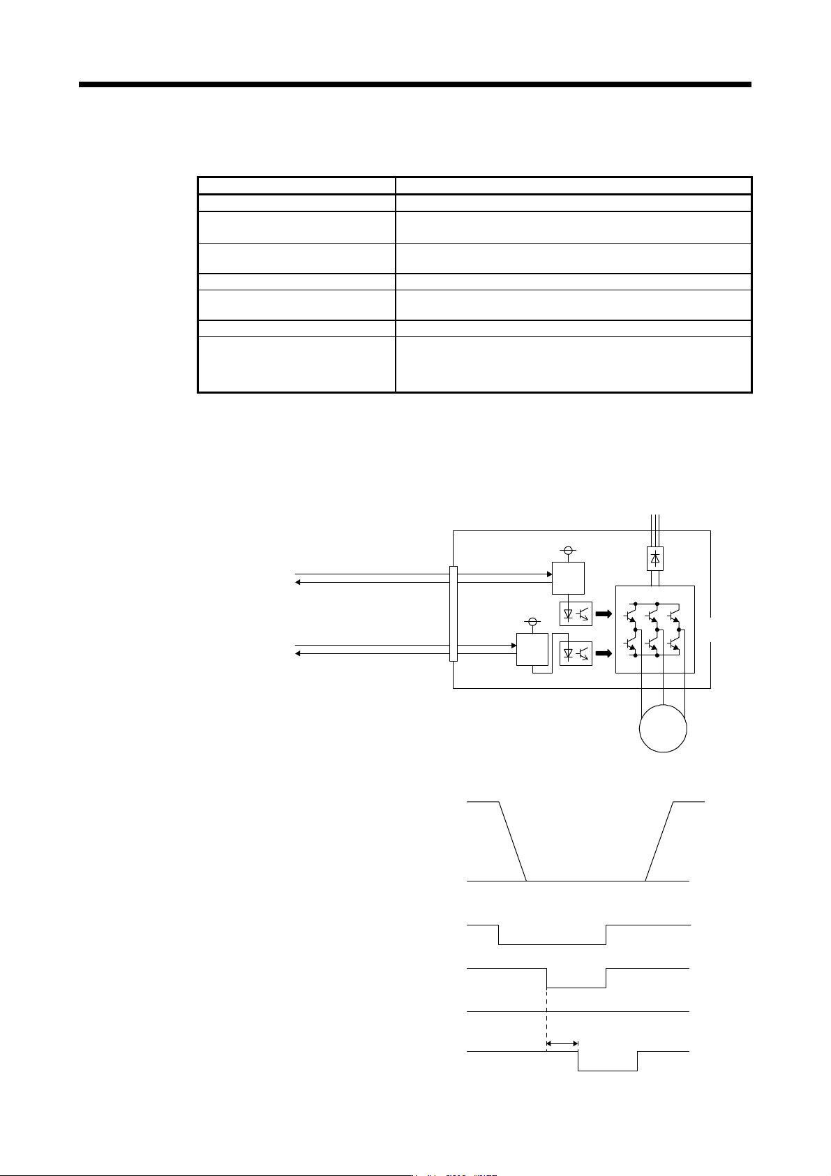
(2) Function block diagram (STO function)
Base power
supply for
upper arm
Base power
supply for
lower arm
Shut-off signal (STO1)
CN8
Monitor signal (TOFB1)
Shut-off signal (STO2)
Monitor signal (TOFB2)
Shut-
off
Shut-
off
Servo motor
M
Power
module
(3) Operation sequence (STO function)
STO1/STO2
ON
OFF
ON
OFF
ON
OFF
ON
OFF
0 r/min
(8 ms)
Servo motor speed
EM2 (Forced stop 2)
Magnetic contactor
Base circuit
(Supplying energy to
the servo motor)