sh030106u.pdf - 第396页
11. OPT ION S AND P ERI PHER AL EQU IPMENT 11 - 75 11.10 Mold ed-case circ uit b reaker s , fuses, magne tic co ntactors CAUTION To prevent the s ervo am plifier from s moke and a fire, s elect a molded-ca se circu it br…
11. OPTIONS AND PERIPHERAL EQUIPMENT
11 - 74
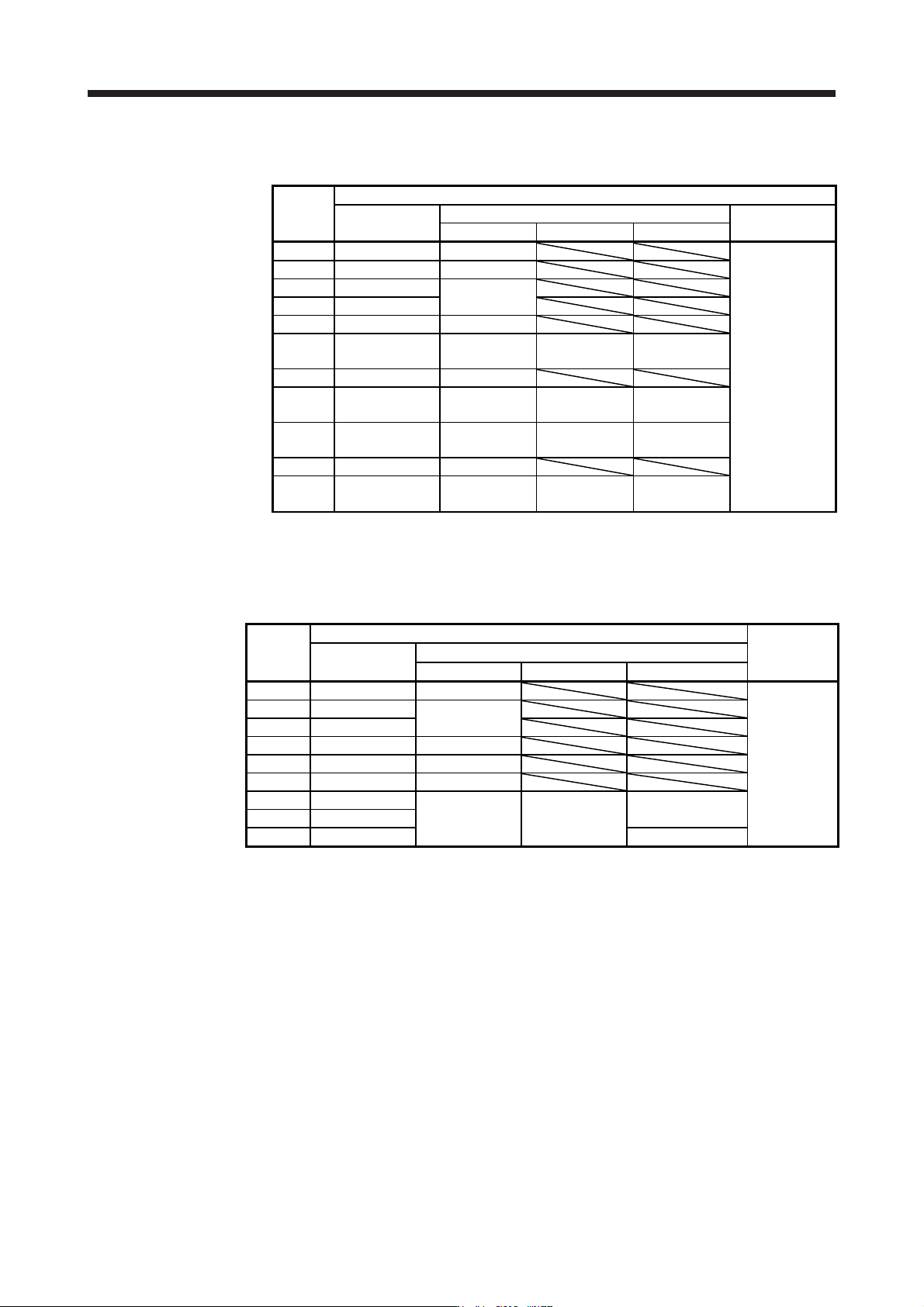
(2) Selection example of crimp terminals
(a) 200 V class
Symbol
Servo amplifier-side crimp terminals
(Note 2) Crimp
terminal
Applicable tool
Manufacturer
Body Head Dice
a FVD5.5-4 YNT-1210S
JST
b (Note 1) 8-4NS YHT-8S
c FVD2-4
YNT-1614
d FVD2-M3
e FVD1.25-M3 YNT-2216
f FVD14-6 YF-1 YNE-38
DH-122
DH-112
g FVD5.5-6 YNT-1210S
h FVD22-6 YF-1 YNE-38
DH-123
DH-113
i FVD38-8 YF-1 YNE-38
DH-124
DH-114
j FVD5.5-8 YNT-1210S
k FVD8-6 YF-1/E-4 YNE-38
DH-121
DH-111
Note 1. Coat the crimpin
g
part with an insulation tube.
2. Some crimp terminals may not be mounted depending on the size. Make sure to use the
recommended ones or equivalent ones.
(b) 400 V class
Symbol
Servo amplifier-side crimp terminals
Manufacturer
Crimp terminal
(Note)
Applicable tool
Body Head Dice
a FVD5.5-4 YNT-1210S
JST
b FVD2-4
YNT-1614
c FVD2-M3
d FVD5.5-6 YNT-1210S
e FVD5.5-8 YNT-1210S
f FVD2-6 YNT-1614
g FVD8-6
YF-1 YNE-38
DH-121/DH-111
h FVD8-8
i FVD14-8 DH-122/DH-112
Note. Some crimp terminals may not be mounted depending on the size. Make sure to use the
recommended ones or equivalent ones.

11. OPTIONS AND PERIPHERAL EQUIPMENT
11 - 75
11.10 Molded-case circuit breakers, fuses, magnetic contactors
CAUTION
To prevent the servo amplifier from smoke and a fire, select a molded-case circuit
breaker which shuts off with high speed.
Always use one molded-case circuit breaker and one magnetic contactor with one
servo amplifier.
POINT
For the selection when the MR-J4-_B-RJ servo amplifier is used with the DC
power supply input, refer to app. 15.4.
11. OPTIONS AND PERIPHERAL EQUIPMENT
11 - 76
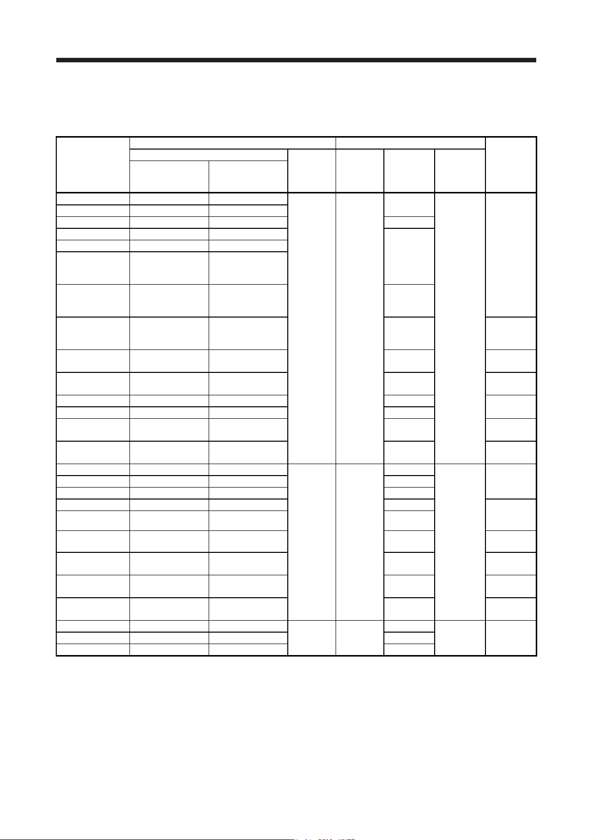
(1) For main circuit power supply
When using a fuse instead of the molded-case circuit breaker, use the one having the specifications
given in this section.
Servo amplifier
Molded-case circuit breaker (Note 1) Fuse
Magnetic
contactor
(Note 2)
Frame, rated current
Voltage AC
[V]
Class Current [A]
Voltage AC
[V]
Power factor
improving reactor is
not used
Power factor
improving reactor is
used
MR-J4-10B(-RJ) 30 A frame 5 A 30 A frame 5 A
240 T
10
300
S-N10
S-T10
MR-J4-20B(-RJ) 30 A frame 5 A 30 A frame 5 A
MR-J4-40B(-RJ) 30 A frame 10 A 30 A frame 5 A 15
MR-J4-60B(-RJ) 30 A frame 15 A 30 A frame 10 A
20
MR-J4-70B(-RJ) 30 A frame 15 A 30 A frame 10 A
MR-J4-100B(-RJ)
(3-phase power
supply input)
30 A frame 15 A 30 A frame 10 A
MR-J4-100B(-RJ)
(1-phase power
supply input)
30 A frame 15 A 30 A frame 15 A 30
MR-J4-200B(-RJ) 30 A frame 20 A 30 A frame 20 A 40
S-N20
(Note 3)
S-T21
MR-J4-350B(-RJ) 30 A frame 30 A 30 A frame 30 A 70
S-N20
S-T21
MR-J4-500B(-RJ) 50 A frame 50 A 50 A frame 50 A 125
S-N35
S-T35
MR-J4-700B(-RJ) 100 A frame 75 A 60 A frame 60 A 150
S-N50
S-T50
MR-J4-11KB(-RJ) 100 A frame 100 A 100 A frame 100 A 200
MR-J4-15KB(-RJ) 125 A frame 125 A 125 A frame 125 A 250
S-N65
S-T65
MR-J4-22KB(-RJ) 225 A frame 175 A 225 A frame 175 A 350
S-N95
S-T100
MR-J4-60B4(-RJ) 30 A frame 5 A 30 A frame 5 A
480 T
10
600
S-N10
S-T10
MR-J4-100B4(-RJ) 30 A frame 10 A 30 A frame 5 A 15
MR-J4-200B4(-RJ) 30 A frame 15 A 30 A frame 10 A 25
MR-J4-350B4(-RJ) 30 A frame 20 A 30 A frame 15 A 35
S-N20
(Note 3)
S-T21
MR-J4-500B4(-RJ) 30 A frame 20 A 30 A frame 20 A 50
MR-J4-700B4(-RJ) 30 A frame 30 A 30 A frame 30 A 65
S-N20
S-T21
MR-J4-11KB4(-RJ) 50 A frame 50 A 50 A frame 50 A 100
S-N25
S-T35
MR-J4-15KB4(-RJ) 60 A frame 60 A 60 A frame 60 A 150
S-N35
S-T35
MR-J4-22KB4(-RJ) 100 A frame 100 A 100 A frame 100 A 175
S-N50
S-T50
MR-J4-10B1(-RJ) 30 A frame 5 A 30 A frame 5 A
240 T
10
300
S-N10
S-T10
MR-J4-20B1(-RJ) 30 A frame 10 A 30 A frame 10 A 15
MR-J4-40B1(-RJ) 30 A frame 15 A 30 A frame 10 A 20
Note 1. When havin
g
the servo amplifier compl
y
with the IEC/EN/UL/CSA standard, refer to app. 4.
2. Use a magnetic contactor with an operation delay time (interval between current being applied to the coil until closure of
contacts
)
of 80 ms or less.
3. S-N18 can be used when auxiliar
y
contact is not required.