sh030106u.pdf - 第599页
17. APPLICATIO N OF FUNCTIONS 17 - 48 a) When a v ibration peak ca n be conf irme d with machine analyz er using MR Conf igurator 2, or external eq uipme nt. 1 Hz Gain characteristics Phase -90 degrees 300 Hz Vibr ation …
17. APPLICATION OF FUNCTIONS
17 - 47
4) Vibration suppression control manual mode
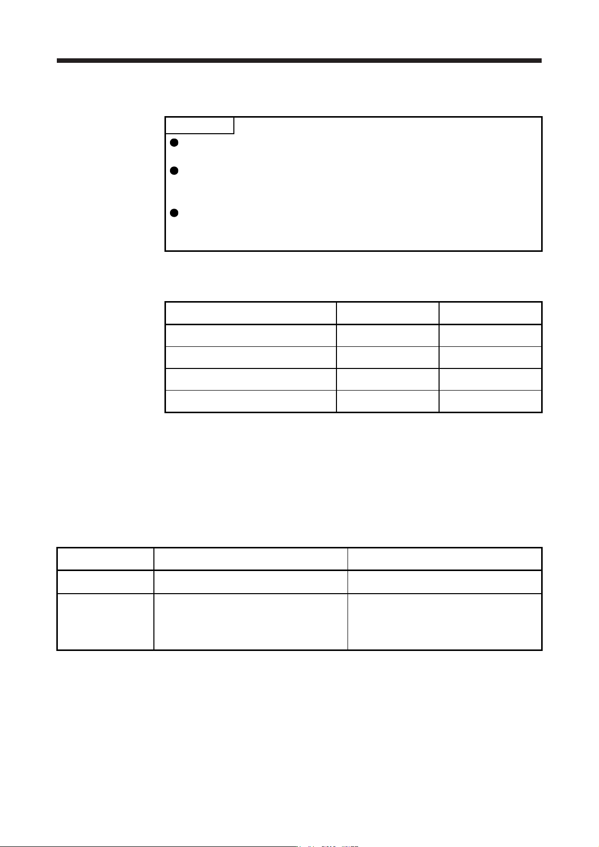
POINT
When load-side vibration does not show up in servo motor-side vibration, the
setting of the servo motor-side vibration frequency does not produce an effect.
When the anti-resonance frequency and resonance frequency can be confirmed
using the machine analyzer or external equipment, do not set the same value
but set different values to improve the vibration suppression performance.
The setting range of [Pr. PB19], [Pr. PB20], [Pr. PX04], and [Pr. PX05] varies,
depending on the value in [Pr. PB07]. If a value out of the range is set, the
vibration suppression control will be disabled.
Measure work-side vibration and device shake with the machine analyzer or external measuring
instrument, and set the following parameters to adjust vibration suppression control manually.
Setting item
Vibration suppression
control 1
Vibration suppression
control 2
Vibration suppression control - Vibration
frequency
[Pr. PB19] [Pr. PX04]
Vibration suppression control - Resonance
frequency
[Pr. PB20] [Pr. PX05]
Vibration suppression control - Vibration
frequency damping
[Pr. PB21] [Pr. PX06]
Vibration suppression control - Resonance
frequency damping
[Pr. PB22] [Pr. PX07]
Step 1. Select "Manual setting (_ _ _ 2)" of "Vibration suppression control 1 tuning mode
selection" in [Pr. PB02] or "Manual setting (_ _ 2 _)" of "Vibration suppression control 2
tuning mode selection" in [Pr. PX03].
Step 2. Set "Vibration suppression control - Vibration frequency" and "Vibration suppression
control - Resonance frequency" as follows.
However, the value of [Pr. PB07 Model loop gain], vibration frequency, and resonance frequency
have the following usable range and recommended range.
Vibration suppression
control
Usable range Recommended setting range
Vibration suppression
control 1
[Pr. PB19] > 1/2π × (0.9 × [Pr. PB07])
[Pr. PB20] > 1/2π × (0.9 × [Pr. PB07])
[Pr. PB19] > 1/2π × (1.5 × [Pr. PB07])
[Pr. PB20] > 1/2π × (1.5 × [Pr. PB07])
Vibration suppression
control 2
When [Pr. PB19] < [Pr. PX04],
[Pr. PX04] > (5.0 + 0.1 × [Pr. PB07])
[Pr. PX05] > (5.0 + 0.1 × [Pr. PB07])
1.1 < [Pr. PX04]/[Pr. PB19] < 5.5
[Pr. PB07] < 2π (0.3 × [Pr. PB19] + 1/8 × [Pr. PX04])
When [Pr. PB19] < [Pr. PX04],
[Pr. PX04], [Pr. PX05] > 6.25 Hz
1.1 < [Pr. PX04]/[Pr. PB19] < 4
[Pr. PB07] < 1/3 × (4 × [Pr. PB19] + 2 × [Pr. PX04])
17. APPLICATION OF FUNCTIONS
17 - 48
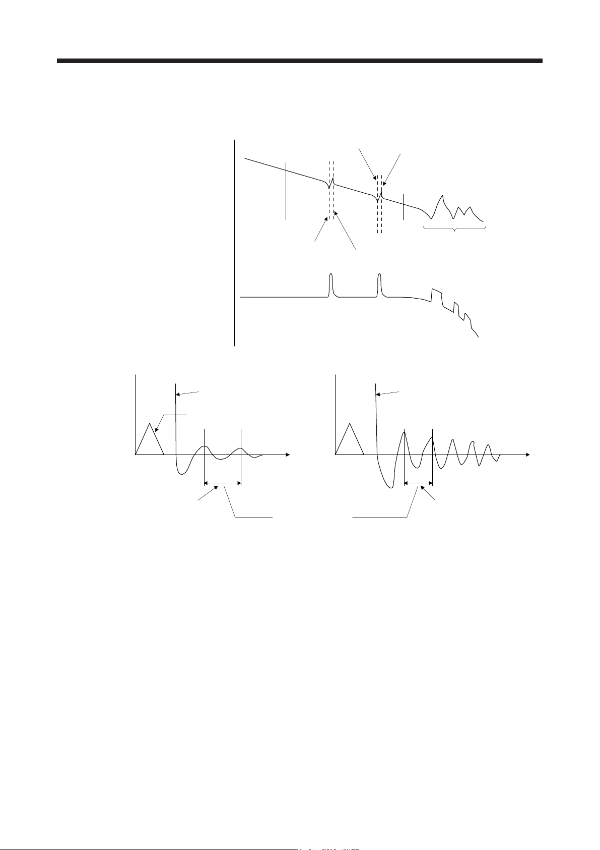
a) When a vibration peak can be confirmed with machine analyzer using MR Configurator2, or
external equipment.
1 Hz
Gain characteristics
Phase
-90 degrees
300 Hz
Vibration suppression control 1 -
Vibration frequency
(anti-resonance frequency)
[Pr. PB19]
Vibration suppression control 1 -
Resonance frequency
[Pr. PB20]
Vibration suppression control 2 -
Vibration frequency
(anti-resonance frequency)
[Pr. PX04]
Vibration suppression control 2 -
Resonance frequency
[Pr. PX05]
Resonance of more than
300 Hz is not the target of control.
b) When vibration can be confirmed using monitor signal or external sensor
t
Motor-side vibration
(droop pulses)
Position command frequency
t
External acceleration pickup signal, etc.
Vibration suppression control -
Vibration frequency
Vibration suppression control -
Resonance frequency
Set the same value.
Vibration cycle [Hz] Vibration cycle [Hz]
Step 3. Fine-adjust "Vibration suppression control - Vibration frequency damping" and "Vibration
suppression control - Resonance frequency damping".
(6) Gain switching function
You can switch gains with the function. You can switch gains during rotation and during stop, and can
use a control command from a controller to switch gains during operation.
(a) Use
The following shows when you use the function.
1) You want to increase the gains during servo-lock but decrease the gains to reduce noise during
rotation.
2) You want to increase the gains during settling to shorten the stop settling time.
3) You want to change the gains using a control command from a controller to ensure stability of the
servo system since the load to motor inertia ratio varies greatly during a stop (e.g. a large load is
mounted on a carrier).
17. APPLICATION OF FUNCTIONS
17 - 49
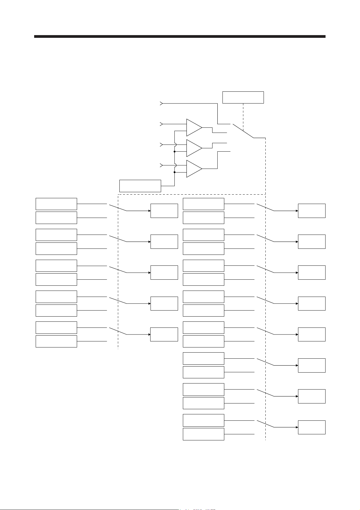
(b) Function block diagram
The control gains, load to motor inertia ratio, and vibration suppression control settings are changed
according to the conditions selected by [Pr. PB26 Gain switching function] and [Pr. PB27 Gain
switching condition].
Command pulse
frequency
+
-
Droop pulses
Model speed
Control command
from controller
Comparator
Changing
CDP
[Pr. PB26]
+
-
+
-
GD2
[Pr. PB06]
GD2B
[Pr. PB29]
Enabled
GD2 value
PG1
[Pr. PB07]
PG1B
[Pr. PX12]
Enabled
PG1 value
PG2
[Pr. PB08]
PG2B
[Pr. PB30]
Enabled
PG2 value
VG2
[Pr. PB09]
VG2B
[Pr. PB31]
Enabled
VG2 value
VIC
[Pr. PB10]
VICB
[Pr. PB32]
Enabled
VIC value
VRF11
[Pr. PB19]
VRF11B
[Pr. PB33]
Enabled
VRF11 value
VRF12
[Pr. PB20]
VRF12B
[Pr. PB34]
Enabled
VRF12 value
CDL
[Pr. PB27]
VRF13
[Pr. PB21]
VRF13B
[Pr. PB35]
Enabled
VRF13 value
VRF14
[Pr. PB22]
VRF14B
[Pr. PB36]
Enabled
VRF14 value
VRF21
[Pr. PX04]
VRF21B
[Pr. PX08]
Enabled
VRF21 value
VRF22
[Pr. PX05]
VRF22B
[Pr. PX09]
Enabled
VRF22 value
VRF23
[Pr. PX06]
VRF23B
[Pr. PX10]
Enabled
VRF23 value
VRF24
[Pr. PX07]
VRF24B
[Pr. PX11]
Enabled
VRF24 value