sh030106u.pdf - 第162页
5. PARAMETE RS 5 - 17 No. Sym bol Name and function Initial value [unit] Setting range PA17 **MSR S ervo motor seri es setting When you use a linear serv o motor, select its model f rom [Pr. P A17] and [ Pr. PA18]. Set t…
5. PARAMETERS
5 - 16
No. Symbol Name and function
Initial
value
[unit]
Setting
range
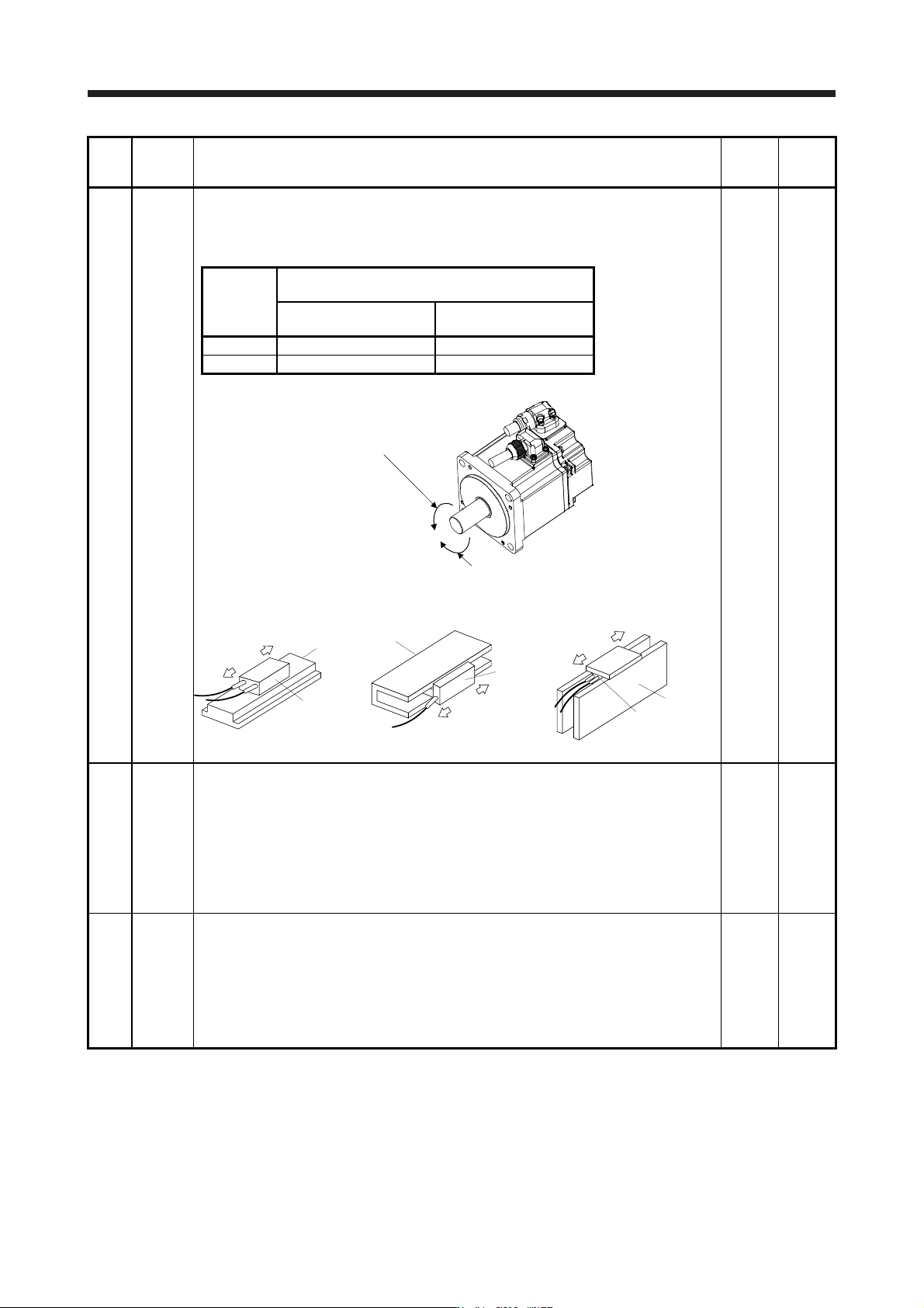
PA14 *POL Rotation direction selection/travel direction selection
Select the rotation direction or travel direction of command input pulses of the rotary servo
motor, linear servo motor and direct drive motor.
For the setting for the master-slave operation function, refer to section 17.2.
0 0 to 1
Setting
value
Servo motor rotation direction/linear servo motor travel
direction
Positioning address
increase
Positioning address
decrease
0 CCW or positive direction CW or negative direction
1 CW or negative direction CCW or positive direction
The following shows the servo motor rotation directions.
Forward rotation (CCW)
Reverse rotation (CW
)
The positive/negative directions of the linear servo motor are as follows.
Secondary side
Primary side
Positive direction
Negative direction
LM-H3/LM-F series
Negative direction
Positive direction
Secondary side
Primary side
LM-U2 series
Negative direction
Positive direction
Table
Primary side
Secondary side
LM-K2 series
PA15 *ENR Encoder output pulses
Set the encoder output pulses from the servo amplifier by using the number of output pulses
per revolution, dividing ratio, or electronic gear ratio. (after multiplication by 4)
To set a numerator of the electronic gear, select "A-phase/B-phase pulse electronic gear
setting (_ _ 3 _)" of "Encoder output pulse setting selection" in [Pr. PC03].
Refer to app. 17 for details.
The maximum output frequency is 4.6 Mpulses/s. Set the parameter within this range.
Depending on the servo motor stop position, the encoder output pulse may turn on and off
repeatedly even if the servo motor is stopped.
4000
[pulse/
rev]
1 to
65535
PA16 *ENR2 Encoder output pulses 2
Set a denominator of the electronic gear for the A/B-phase pulse output.
To set a denominator of the electronic gear, select "A-phase/B-phase pulse electronic gear
setting (_ _ 3 _)" of "Encoder output pulse setting selection" in [Pr. PC03].
Refer to app. 17 for details.
The maximum output frequency is 4.6 Mpulses/s. Set the parameter within this range.
Depending on the servo motor stop position, the encoder output pulse may turn on and off
repeatedly even if the servo motor is stopped.
1
1 to
65535
5. PARAMETERS
5 - 17
No. Symbol Name and function
Initial
value
[unit]
Setting
range
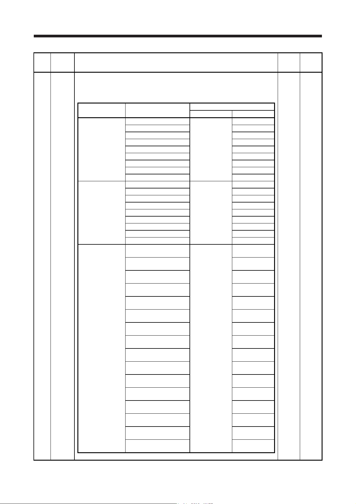
PA17 **MSR Servo motor series setting
When you use a linear servo motor, select its model from [Pr. PA17] and [Pr. PA18]. Set this
and [Pr. PA18] at a time.
Refer to the following table for settings.
0000h
Refer to
the
"Name
and
function"
column.
Linear servo motor
series
Linear servo motor
(primary side)
Parameter
[Pr. PA17] setting [Pr. PA18] setting
LM-H3
LM-H3P2A-07P-BSS0
00BBh
2101h
LM-H3P3A-12P-CSS0 3101h
LM-H3P3B-24P-CSS0 3201h
LM-H3P3C-36P-CSS0 3301h
LM-H3P3D-48P-CSS0 3401h
LM-H3P7A-24P-ASS0 7101h
LM-H3P7B-48P-ASS0 7201h
LM-H3P7C-72P-ASS0 7301h
LM-H3P7D-96P-ASS0 7401h
LM-U2
LM-U2PAB-05M-0SS0
00B4h
A201h
LM-U2PAD-10M-0SS0 A401h
LM-U2PAF-15M-0SS0 A601h
LM-U2PBB-07M-1SS0 B201h
LM-U2PBD-15M-1SS0 B401h
LM-U2PBF-22M-1SS0 2601h
LM-U2P2B-40M-2SS0 2201h
LM-U2P2C-60M-2SS0 2301h
LM-U2P2D-80M-2SS0 2401h
LM-F
LM-FP2B-06M-1SS0
(natural cooling)
00B2h
2201h
LM-FP2D-12M-1SS0
(natural cooling)
2401h
LM-FP2F-18M-1SS0
(natural cooling)
2601h
LM-FP4B-12M-1SS0
(natural cooling)
4201h
LM-FP4D-24M-1SS0
(natural cooling)
4401h
LM-FP4F-36M-1SS0
(natural cooling)
4601h
LM-FP4H-48M-1SS0
(natural cooling)
4801h
LM-FP5H-60M-1SS0
(natural cooling)
5801h
LM-FP2B-06M-1SS0
(liquid cooling)
2202h
LM-FP2D-12M-1SS0
(liquid cooling)
2402h
LM-FP2F-18M-1SS0
(liquid cooling)
2602h
LM-FP4B-12M-1SS0
(liquid cooling)
4202h
LM-FP4D-24M-1SS0
(liquid cooling)
4402h
LM-FP4F-36M-1SS0
(liquid cooling)
4602h
LM-FP4H-48M-1SS0
(liquid cooling)
4802h
LM-FP5H-60M-1SS0
(liquid cooling)
5802h
5. PARAMETERS
5 - 18
No. Symbol Name and function
Initial
value
[unit]
Setting
range
PA17 **MSR 0000h
Refer to
the
"Name
and
function"
column.
Linear servo motor
series
Linear servo motor
(primary side)
Parameter
LM-K2P1A-01M-2SS1 1101h
LM-K2P1C-03M-2SS1 1301h
LM-K2P2A-02M-1SS1 2101h
LM-K2 LM-K2P2C-07M-1SS1 00B8h 2301h
LM-K2P2E-12M-1SS1 2501h
LM-K2P3C-14M-1SS1 3301h
LM-K2P3E-24M-1SS1 3501h
PA18 **MTY Servo motor type setting
When you use a linear servo motor, select its model from [Pr. PA17] and [Pr. PA18]. Set this
and [Pr. PA17] at a time.
Refer to the table of [Pr. PA17] for settings.
0000h
Refer to
the
"Name
and
function"
column
of [Pr.
PA17].
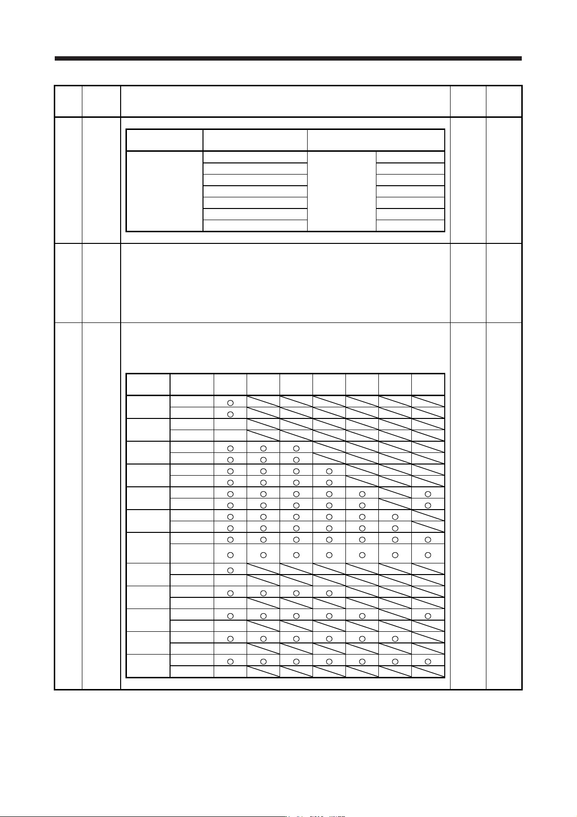
PA19 *BLK Parameter writing inhibit
Select a reference range and writing range of the parameter.
Refer to table 5.3 for settings.
00ABh
Refer to
the
"Name
and
function"
column.
Table 5.3 [Pr. PA19] setting value and reading/writing range
PA19
Setting
operation
PA PB PC PD PE PF PL
Other than
below
Reading
Writing
000Ah
Reading Only 19
Writing Only 19
000Bh
Reading
Writing
000Ch
Reading
Writing
000Fh
Reading
Writing
00AAh
Reading
Writing
00ABh
(initial
value)
Reading
Writing
100Bh
Reading
Writing Only 19
100Ch
Reading
Writing Only 19
100Fh
Reading
Writing Only 19
10AAh
Reading
Writing Only 19
10ABh
Reading
Writing Only 19