sh030106u.pdf - 第484页
14. USIN G A LINEAR SER VO MOTOR 14 - 17 3) Linear s ervo mo tor mov ement (wh en FLS ( Upper s trok e limit) or RL S (Lower stroke li mit) is off) When FLS or RLS is off at serv o-on, the ma gnetic pole det ectio n is c…
14. USING A LINEAR SERVO MOTOR
14 - 16
(a) For the incremental linear encoder
POINT
For the incremental linear encoder, the magnetic pole detection is required every
time the power is turned on.
By turning on the servo-on command from the controller after the power-on, the magnetic pole
detection is automatically carried out. Therefore, there is no need to set the parameter (first digit of
[Pr. PL01]) for executing the magnetic pole detection.
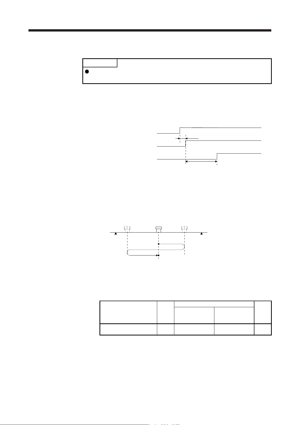
1) Timing chart
15 s or less
ON
OFF
ON
OFF
ON
OFF
95 ms
Servo-on command
Base circuit
RD (Ready)
Magnetic pole detection time (Note)
Note. The magnetic pole detection time indicates the operation time when FLS (Upper
stroke limit
)
and RLS
(
Lower stroke limit
)
are on.
2) Linear servo motor movement (when FLS (Upper stroke limit) and RLS (Lower stroke limit) are
on)
RLS
(Note 1)
FLS
(Note 1)
(Note 2)
Magnetic pole detection completion position
Servo-on position
(Magnetic pole detection start position)
Note 1. When you turn off FLS (Upper stroke limit) or RLS (Lower stroke limit) during the magnetic pole detection, the operation of the
magnetic pole detection is carried on to the opposite direction. When both FLS and RLS are off, [AL. 27 Initial magnetic pole
detection error] occurs.
2. The followin
g
shows the pitch a
g
ainst the ma
g
netic pole.
Linear servo motor series
LM-H3
LM-F
LM-U2
LM-K2
Medium thrust
(Continuous thrust:
Less than 400 N)
Large thrust
(Continuous thrust:
400 N or more)
Pitch against magnetic pole
[mm]
48 30 60 48
14. USING A LINEAR SERVO MOTOR
14 - 17
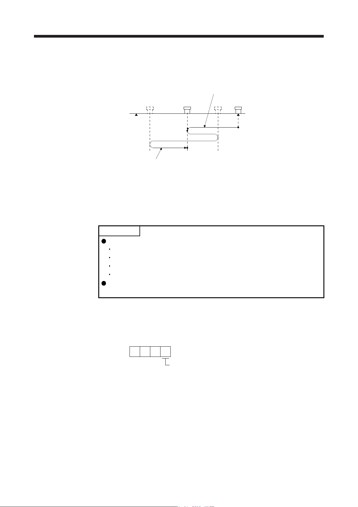
3) Linear servo motor movement (when FLS (Upper stroke limit) or RLS (Lower stroke limit) is off)
When FLS or RLS is off at servo-on, the magnetic pole detection is carried out as follows.
RLS FLS
(Note)
Magnetic pole detection completion position
Magnetic pole detection
start position
Servo-on
position
The linear servo motor moves to a
magnetic pole detection start position
upon servo-on, and the magnetic pole
detection is executed.
The linear servo motor reciprocates several times and returns
to the magnetic pole detection start position to complete the
magnetic pole detection and to go into the servo-lock status.
A
t this time, there may be a gap, approximately a quarter of
the pitch against magnetic pole, from the start position.
Note. For the pitch a
g
ainst ma
g
netic pole, refer to
(
3
)
(
a
)
2
)
Note 2 in this section.
(b) For the absolute position linear encoder
POINT
The magnetic pole detection is required in the following timings.
When the system is set up (at the first startup of equipment)
After a servo amplifier is replaced
After a linear servo motor (primary-side or secondary-side) is replaced
After a linear encoder (scale or head) is replaced or remounted
If a gap is generated to the positional relation between the linear encoder and
the linear servo motor, perform the magnetic pole detection again.
Perform the magnetic pole detection in the following procedure.
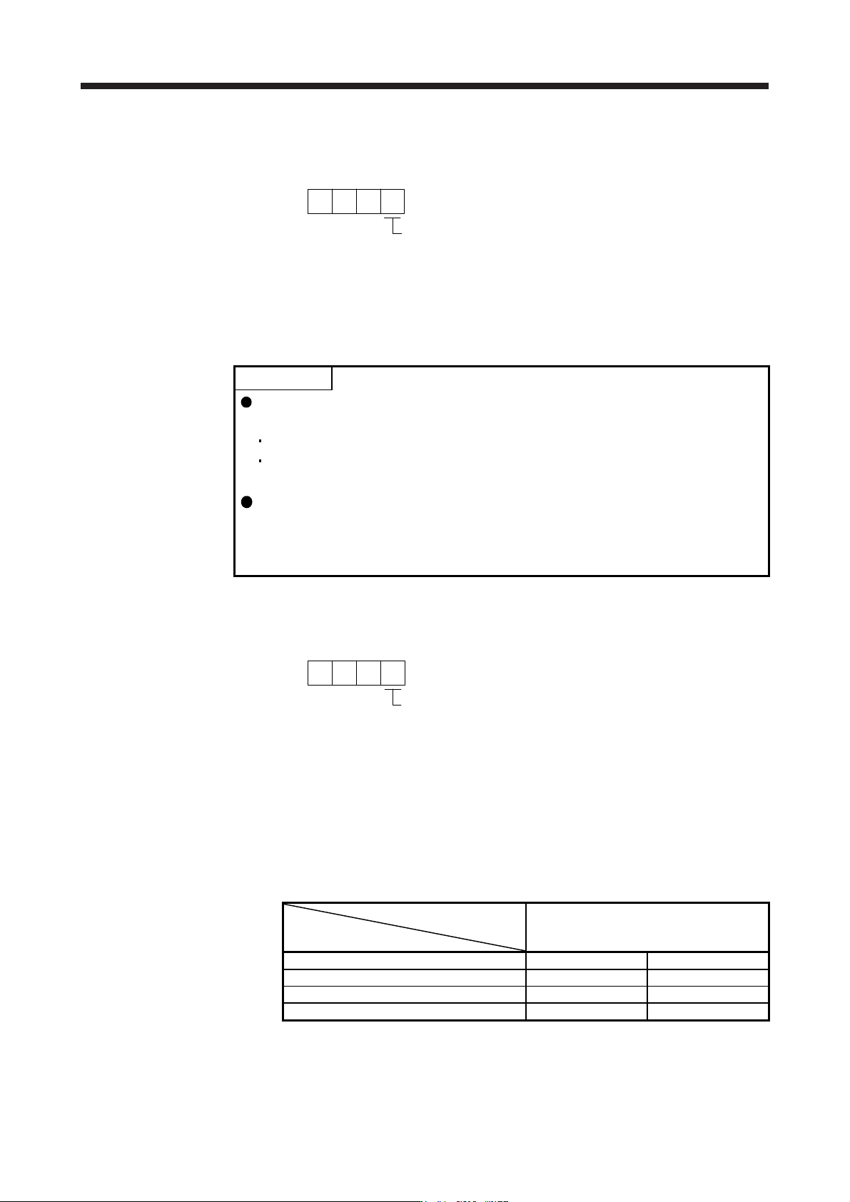
1) Set [Pr. PL01 Linear servo motor/DD motor function selection 1] to "_ _ _ 1" (Magnetic pole
detection at first servo-on).
[Pr. PL01]
Magnetic pole detection at first servo-on (Initial value
)
1
2) Execute the magnetic pole detection. (Refer to (3) (a) in this section.)
14. USING A LINEAR SERVO MOTOR
14 - 18
3) After the completion of the magnetic pole detection, change [Pr. PL01] to "_ _ _ 0" (Magnetic pole
detection disabled).
[Pr. PL01]
Magnetic pole detection disabled
0
After the magnetic pole detection, by disabling the magnetic pole detection function with [Pr. PL01],
the magnetic pole detection after each power-on is not required.
(4) Magnetic pole detection method setting
POINT
In the following cases, set the magnetic pole detection method to the minute
position detection method.
When a shorten travel distance at the magnetic pole detection is required
When the magnetic pole detection by the position detection method is not
completed
When a linear encoder with a resolution smaller than 0.05 μm is used and the
magnetic pole detection does not complete normally by minute position
detection method, select "Enabled (1 _ _ _)" of "Minute position detection
method - High-resolution encoder selection" in [Pr. PL08].
Set the magnetic pole detection method using the first digit of [Pr. PL08] (Magnetic pole detection
method selection).
[Pr. PL08]
Magnetic pole detection method selection
0: Position detection method
4: Minute position detection method
(5) Setting of the magnetic pole detection voltage level by the position detection method
For the magnetic pole detection by the position detection method, set the voltage level with [Pr. PL09
Magnetic pole detection voltage level]. For the magnetic pole detection by the minute position detection
method, the voltage level setting is not required.
(a) Guideline of parameter settings
Set the parameters by referring to the following table.
[Pr. PL09] setting
(guide value)
Servo status
Small ← Medium → Large
(10 or less (initial value) 50 or more)
Thrust at operation Small Large
Overload, overcurrent alarm Seldom occurs Frequently occurs
Magnetic pole detection alarm Frequently occurs Seldom occurs
Magnetic pole detection accuracy Low High