sh030106u.pdf - 第160页
5. PARAMETE RS 5 - 15 No. Sym bol Name and function Initial value [unit] Setting range PA09 RSP Auto tuni ng response Set a res ponse of the auto tuni ng. 16 1 to 40 Setting value Machi ne characterist ic Setting value M…
5. PARAMETERS
5 - 14
No. Symbol Name and function
Initial
value
[unit]
Setting
range
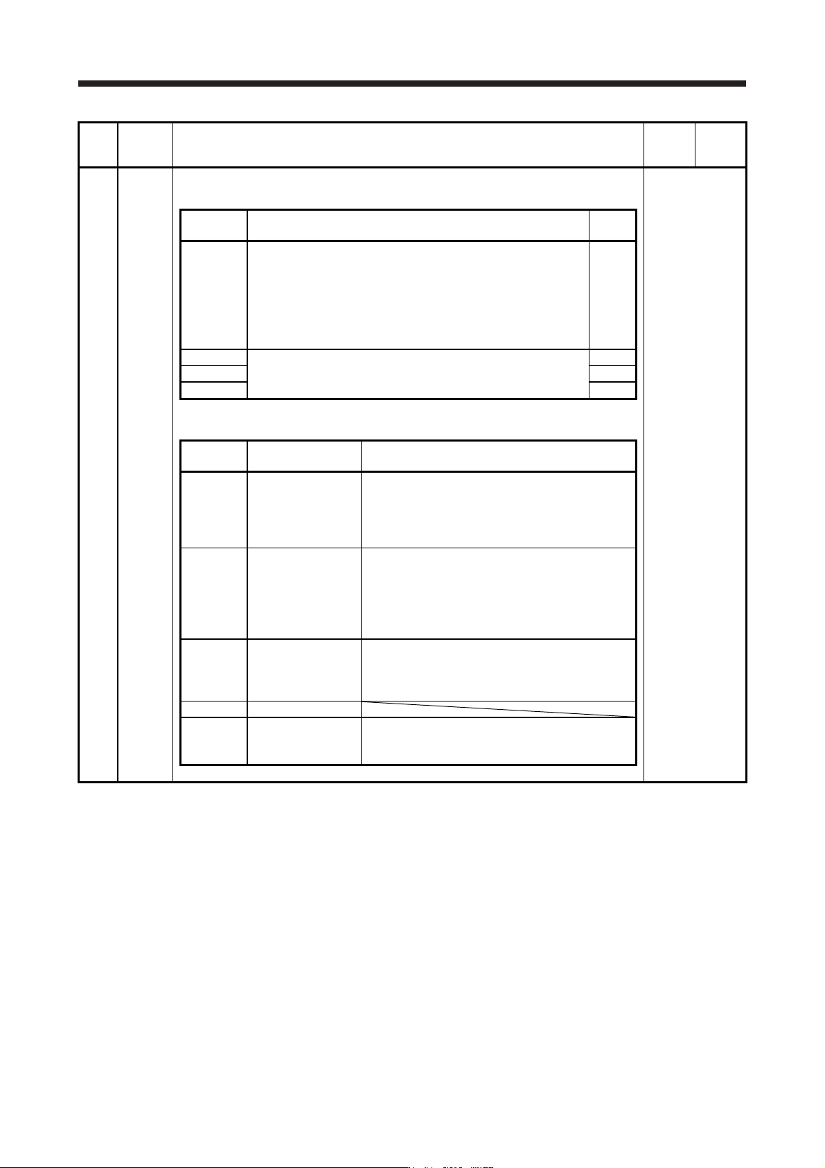
PA08 ATU Auto tuning mode
Select the gain adjustment mode.
Refer to the
"Name and
function" column.
Setting
digit
Explanation
Initial
value
_ _ _ x Gain adjustment mode selection
0: 2 gain adjustment mode 1 (interpolation mode)
1: Auto tuning mode 1
2: Auto tuning mode 2
3: Manual mode
4: 2 gain adjustment mode 2
Refer to table 5.2 for details.
1h
_ _ x _ For manufacturer setting 0h
_ x _ _ 0h
x _ _ _ 0h
Table 5.2 Gain adjustment mode selection
Setting
value
Gain adjustment
mode
Automatically adjusted parameter
_ _ _ 0
2 gain adjustment
mode 1
(interpolation mode)
[Pr. PB06 Load to motor inertia ratio/load to motor
mass ratio]
[Pr. PB08 Position loop gain]
[Pr. PB09 Speed loop gain]
[Pr. PB10 Speed integral compensation]
_ _ _ 1 Auto tuning mode 1
[Pr. PB06 Load to motor inertia ratio/load to motor
mass ratio]
[Pr. PB07 Model loop gain]
[Pr. PB08 Position loop gain]
[Pr. PB09 Speed loop gain]
[Pr. PB10 Speed integral compensation]
_ _ _ 2 Auto tuning mode 2 [Pr. PB07 Model loop gain]
[Pr. PB08 Position loop gain]
[Pr. PB09 Speed loop gain]
[Pr. PB10 Speed integral compensation]
_ _ _ 3 Manual mode
_ _ _ 4
2 gain adjustment
mode 2
[Pr. PB08 Position loop gain]
[Pr. PB09 Speed loop gain]
[Pr. PB10 Speed integral compensation]
5. PARAMETERS
5 - 15
No. Symbol Name and function
Initial
value
[unit]
Setting
range
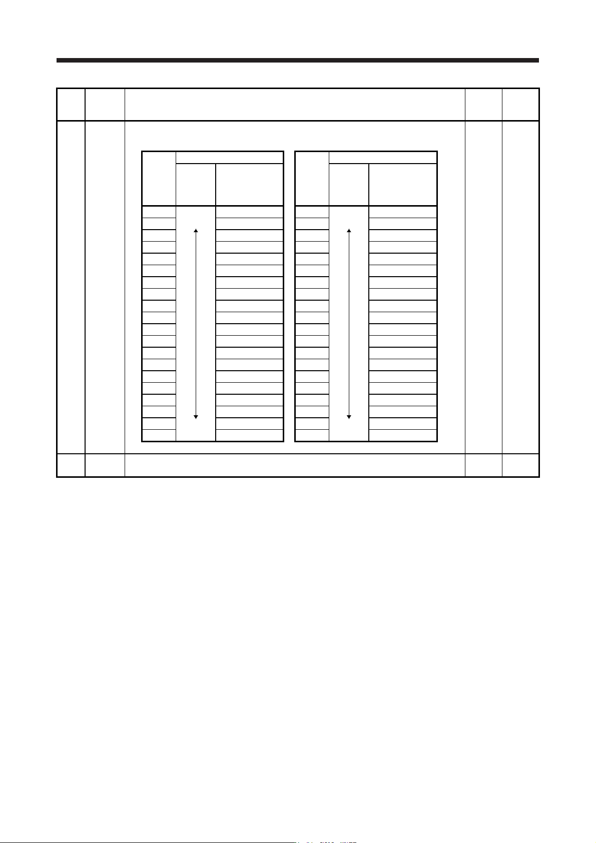
PA09 RSP Auto tuning response
Set a response of the auto tuning.
16 1 to 40
Setting
value
Machine characteristic
Setting
value
Machine characteristic
Response
Guideline for
machine
resonance
frequency [Hz]
Response
Guideline for
machine
resonance
frequency [Hz]
1
Low
response
Middle
response
2.7 21
Middle
response
High
response
67.1
2 3.6 22 75.6
3 4.9 23 85.2
4 6.6 24 95.9
5 10.0 25 108.0
6 11.3 26 121.7
7 12.7 27 137.1
8 14.3 28 154.4
9 16.1 29 173.9
10 18.1 30 195.9
11 20.4 31 220.6
12 23.0 32 248.5
13 25.9 33 279.9
14 29.2 34 315.3
15 32.9 35 355.1
16 37.0 36 400.0
17 41.7 37 446.6
18 47.0 38 501.2
19 52.9 39 571.5
20 59.6 40 642.7
PA10 INP In-position range
Set an in-position range per command pulse.
1600
[pulse]
0 to
65535
5. PARAMETERS
5 - 16
No. Symbol Name and function
Initial
value
[unit]
Setting
range
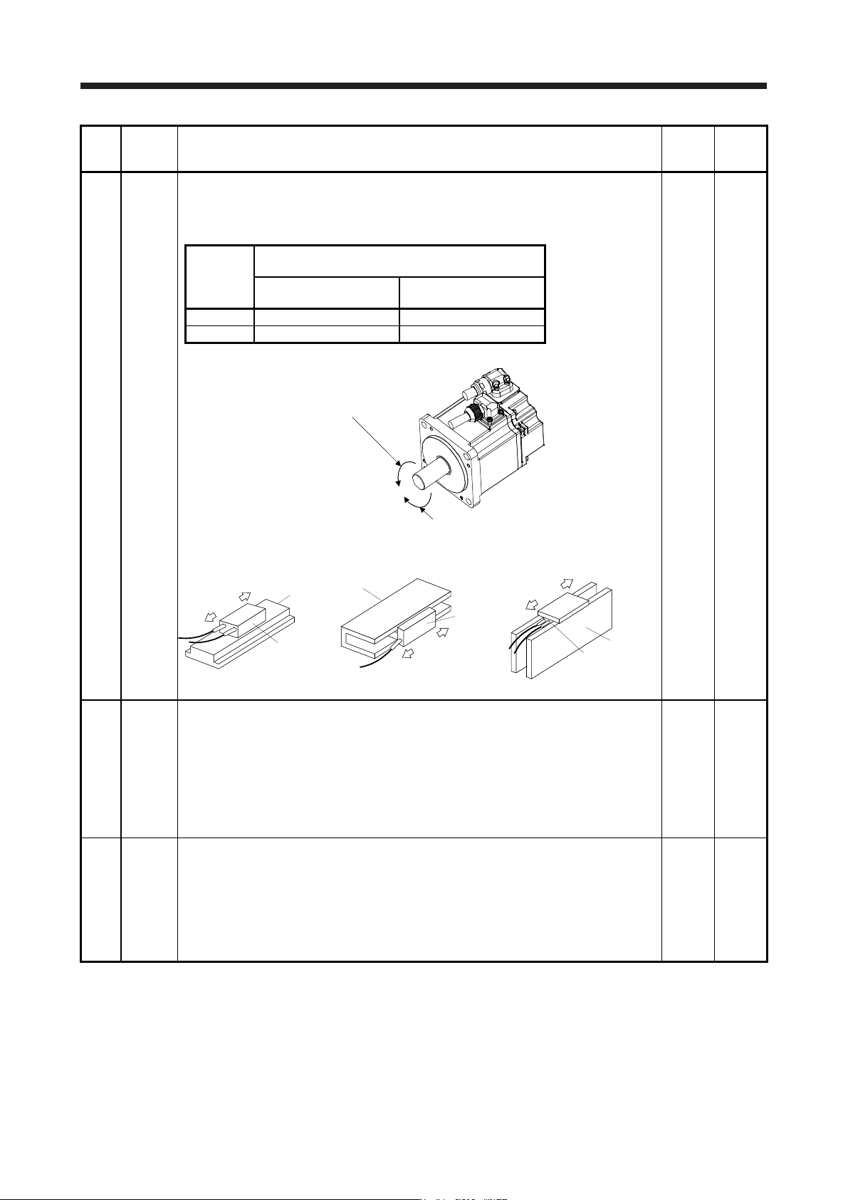
PA14 *POL Rotation direction selection/travel direction selection
Select the rotation direction or travel direction of command input pulses of the rotary servo
motor, linear servo motor and direct drive motor.
For the setting for the master-slave operation function, refer to section 17.2.
0 0 to 1
Setting
value
Servo motor rotation direction/linear servo motor travel
direction
Positioning address
increase
Positioning address
decrease
0 CCW or positive direction CW or negative direction
1 CW or negative direction CCW or positive direction
The following shows the servo motor rotation directions.
Forward rotation (CCW)
Reverse rotation (CW
)
The positive/negative directions of the linear servo motor are as follows.
Secondary side
Primary side
Positive direction
Negative direction
LM-H3/LM-F series
Negative direction
Positive direction
Secondary side
Primary side
LM-U2 series
Negative direction
Positive direction
Table
Primary side
Secondary side
LM-K2 series
PA15 *ENR Encoder output pulses
Set the encoder output pulses from the servo amplifier by using the number of output pulses
per revolution, dividing ratio, or electronic gear ratio. (after multiplication by 4)
To set a numerator of the electronic gear, select "A-phase/B-phase pulse electronic gear
setting (_ _ 3 _)" of "Encoder output pulse setting selection" in [Pr. PC03].
Refer to app. 17 for details.
The maximum output frequency is 4.6 Mpulses/s. Set the parameter within this range.
Depending on the servo motor stop position, the encoder output pulse may turn on and off
repeatedly even if the servo motor is stopped.
4000
[pulse/
rev]
1 to
65535
PA16 *ENR2 Encoder output pulses 2
Set a denominator of the electronic gear for the A/B-phase pulse output.
To set a denominator of the electronic gear, select "A-phase/B-phase pulse electronic gear
setting (_ _ 3 _)" of "Encoder output pulse setting selection" in [Pr. PC03].
Refer to app. 17 for details.
The maximum output frequency is 4.6 Mpulses/s. Set the parameter within this range.
Depending on the servo motor stop position, the encoder output pulse may turn on and off
repeatedly even if the servo motor is stopped.
1
1 to
65535