sh030106u.pdf - 第336页
11. OPT ION S AND P ERI PHER AL EQU IPMENT 11 - 15 (2) Linear s ervo mo tor (a) Thrust and energy cal culation Linear servo moto r secondary-side (magnet) Load V M 1 M 2 Linear servo motor primary-side (coil) Linear serv…

11. OPTIONS AND PERIPHERAL EQUIPMENT
11 - 14
(b) Losses of servo motor and servo amplifier in regenerative mode
The following table lists the efficiencies and other data of the servo motor and servo amplifier in the
regenerative mode.
Servo amplifier
Inverse
efficiency [%]
Capacitor
charging [J]
Servo amplifier
Inverse
efficiency [%]
Capacitor
charging [J]
MR-J4-10B(-RJ) 55 9 MR-J4-60B4(-RJ) 85 12
MR-J4-20B(-RJ) 75 9 MR-J4-100B4(-RJ) 85 12
MR-J4-40B(-RJ) 85 11 MR-J4-200B4(-RJ) 85 25
MR-J4-60B(-RJ) 85 11 MR-J4-350B4(-RJ) 85 43
MR-J4-70B(-RJ) 85 18 MR-J4-500B4(-RJ) 90 45
MR-J4-100B(-RJ) 85 18 MR-J4-700B4(-RJ) 90 70
MR-J4-200B(-RJ) 85 36 MR-J4-11KB4(-RJ) 90 120
MR-J4-350B(-RJ) 85 40 MR-J4-15KB4(-RJ) 90 170
MR-J4-500B(-RJ) 90 45 MR-J4-22KB4(-RJ) 90 250
MR-J4-700B(-RJ) 90 70 MR-J4-10B1(-RJ) 55 4
MR-J4-11KB(-RJ) 90 120 MR-J4-20B1(-RJ) 75 4
MR-J4-15KB(-RJ) 90 170 MR-J4-40B1(-RJ) 85 10
MR-J4-22KB(-RJ) 90 250
Inverse efficiency (η
m
): Efficiency including some efficiencies of the servo motor and servo amplifier
when rated (regenerative) torque is generated at rated speed. Efficiency
varies with the speed and generated torque. Since the characteristics of the
electrolytic capacitor change with time, allow for approximately 10% higher
inverse efficiency.
Capacitor charging (Ec): Energy charged into the electrolytic capacitor in the servo amplifier
Subtract the capacitor charging from the result of multiplying the sum total of regenerative energies
by the inverse efficiency to calculate the energy consumed by the regenerative option.
ER [J] = η
m
• Es - Ec
Calculate the power consumption of the regenerative option on the basis of single-cycle operation
period tf [s] to select the necessary regenerative option.
PR [W] = ER/tf
11. OPTIONS AND PERIPHERAL EQUIPMENT
11 - 15
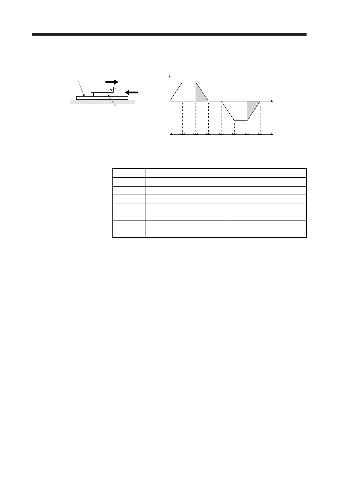
(2) Linear servo motor
(a) Thrust and energy calculation
Linear servo moto
r
secondary-side (magnet)
Load
V
M
1
M2
Linear servo motor
primary-side (coil)
Linear servo motor
F
t
2)
1)
V
3)
4)
Positive
direction
6)
5) 7)
Negative
direction
8)
Time
Feed speed
t
psa1 t1 tpsd1 t2 tpsa2 t3 t4tpsd2
The following shows equations of the linear servo motor thrust and energy at the driving pattern
above.
Section Thrust F of linear servo motor [N] Energy E [J]
1) F
1
= (M
1
+ M
2
) • V/t
psa1
+ F
t
E
1
= V/2 • F
1
• t
psa1
2) F
2
= F
1
E
2
= V • F
2
• t
1
3) F
3
= -(M
1
+ M
2
) • V/t
psd1
+ F
t
E
3
= V/2 • F
3
• t
psd1
4), 8) F
4,
F
8
= 0 E
4
, E
8
= 0 (No regeneration)
5) F
5
= (M
1
+ M
2
) • V/t
psa2
+ F
t
E
5
= V/2 • F
5
• t
psa2
6) F
6
= F
t
E
6
= V • F
6
• t
3
7) F
7
= -(M
1
+ M
2
) • V/t
psd2
+ F
t
E
7
= V/2 • F
7
• t
psd2
From the calculation results in 1) to 8), find the absolute value (Es) of the sum total of negative
energies.
(b) Losses of servo motor and servo amplifier in regenerative mode
For inverse efficiency and capacitor charging energy, refer to (1) (b) in this section.
(c) Regenerative energy calculation
Subtract the capacitor charging from the result of multiplying the sum total of regenerative energies
by the inverse efficiency to calculate the energy consumed by the regenerative resistor.
ER [J] = η • Es - Ec
From the total of ER's whose subtraction results are positive and one-cycle period, the power
consumption PR [W] of the regenerative option can be calculated with the following equation.
PR [W] = total of positive ER's/one-cycle operation period (tf)
Select a regenerative option from the PR value. Regenerative option is not required when the energy
consumption is equal to or less than the built-in regenerative energy.
11. OPTIONS AND PERIPHERAL EQUIPMENT
11 - 16
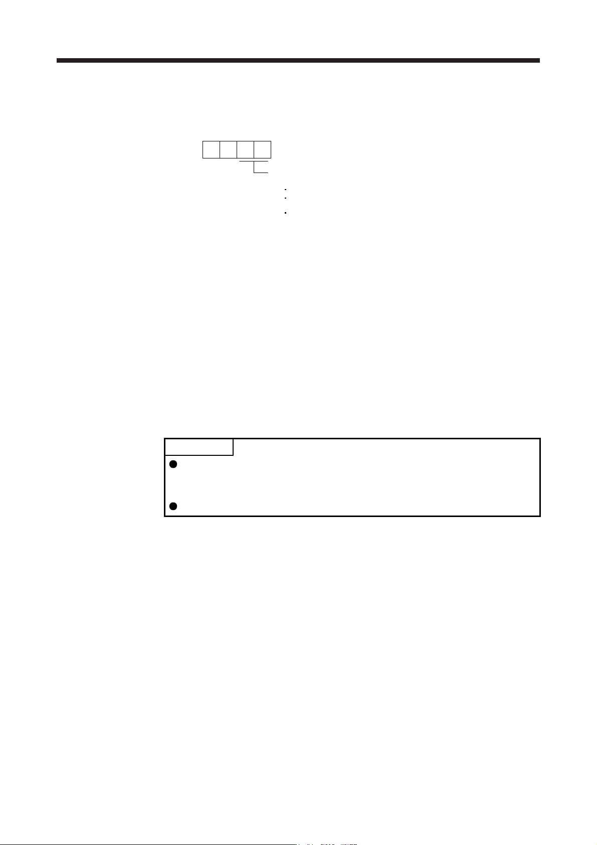
11.2.3 Parameter setting
Set [Pr. PA02] according to the option to be used.
Regenerative option selection
00: Regenerative option is not used.
For servo amplifier of 100 W, regenerative resistor is not used.
Built-in regenerative resistors are used on servo amplifiers with a
capacity of 0.2 kW to 7 kW.
Supplied regenerative resistors or regenerative option is used
with the servo amplifier of 11 kW to 22 kW.
01: FR-BU2/FR-BU2-H/FR-RC/FR-RC-H/FR-CV/FR-CV-H/FR-XC/FR-XC-H
02: MR-RB032
03: MR-RB12
04: MR-RB32
05: MR-RB30
06: MR-RB50 (Cooling fan is required)
08: MR-RB31
09: MR-RB51 (Cooling fan is required)
0B: MR-RB3N
0C: MR-RB5N (Cooling fan is required)
80: MR-RB1H-4
81: MR-RB3M-4 (Cooling fan is required.)
82: MR-RB3G-4 (Cooling fan is required.)
83: MR-RB5G-4 (Cooling fan is required.)
84: MR-RB34-4 (Cooling fan is required.)
85: MR-RB54-4 (Cooling fan is required.)
91: MR-RB3U-4 (Cooling fan is required.)
92: MR-RB5U-4 (Cooling fan is required.)
FA: When the supplied regenerative resistors or the regenerative
option is cooled by the cooling fan to increase the ability with
the servo amplifier of 11 kW to 22 kW.
00
[Pr. PA02]
11.2.4 Connection of regenerative option
POINT
When MR-RB50, MR-RB51, MR-RB5N, MR-RB3M-4, MR-RB3G-4, MR-RB5G-
4, MR-RB34-4, MR-RB54-4, MR-RB5K-4, or MR-RB6K-4 is used, a cooling fan
is required to cool it. The cooling fan should be prepared by the customer.
For the wire sizes used for wiring, refer to section 11.9.
The regenerative option generates heat of 100 ˚C higher than the ambient temperature. Fully consider heat
dissipation, installation position, wires used, etc. before installing the option. For wiring, use flame-resistant
wires or make the wires flame-resistant and keep them away from the regenerative option. Use twisted wires
with a maximum length of 5 m for a connection with the servo amplifier.