sh030106u.pdf - 第509页
15. USIN G A DI REC T DRIV E MOTOR 15 - 6 15.3.2 M agnetic p ole detec tion POINT The magn etic pol e detect ion is not req uired for the c onfigure d abs olute p osit ion detection syst em where the Z-phase pulse of t h…
15. USING A DIRECT DRIVE MOTOR
15 - 5
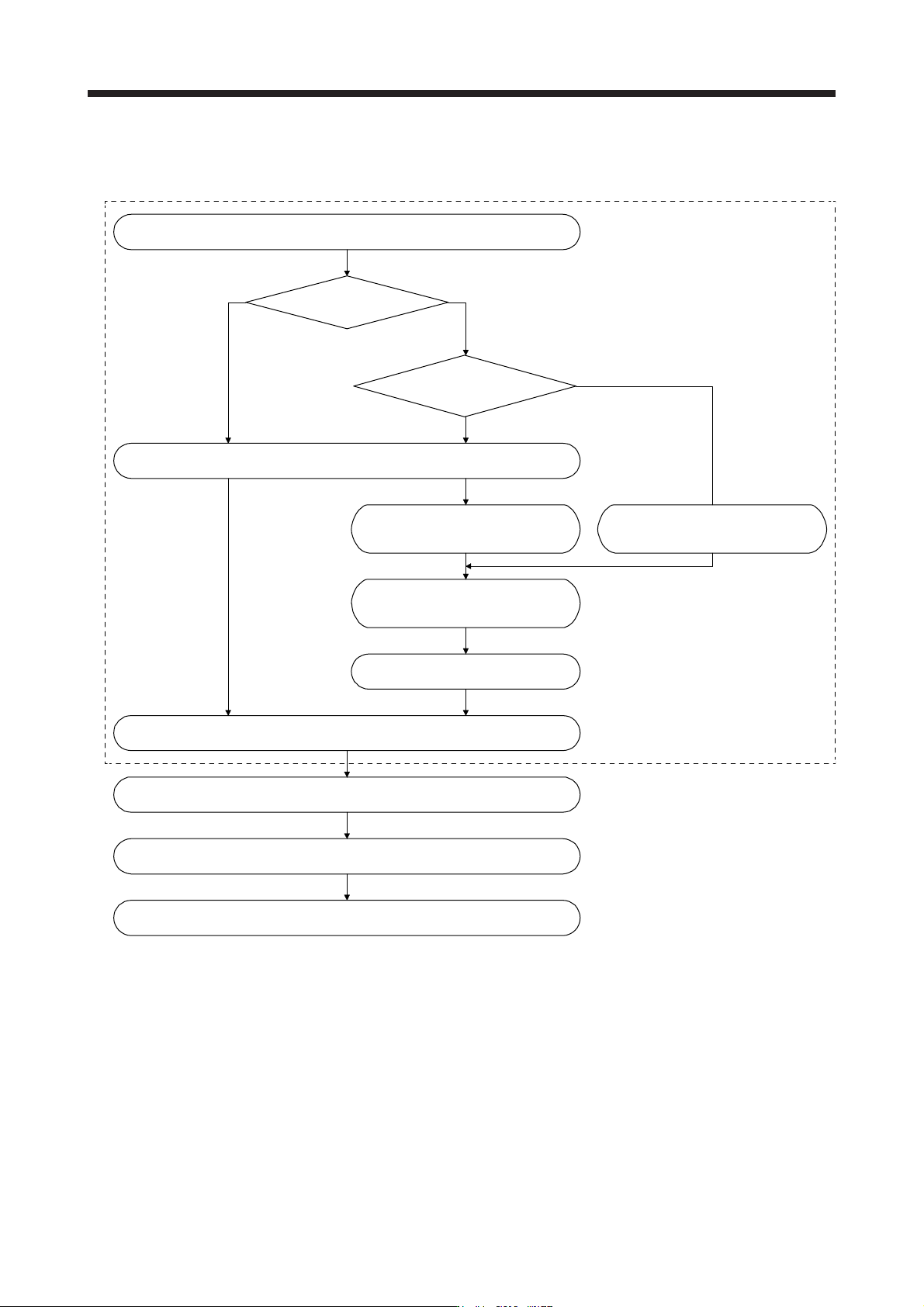
15.3.1 Startup procedure
Start up the direct drive servo system in the following procedure.
Absolute position detection system
Installation and wiring
Z-phase pulse of the direct drive motor
is turned on by the JOG operation.
(Notes 1 and 2)
Perform the magnetic pole detection. (Refer to section 15.3.2.) (Note 1)
Absolute position
detection system?
Incremental system
Can you manually turn
on the Z-phase pulse of the
direct drive motor?
Change the setting to disable the
magnetic pole detection.
(Refer to section 15.3.2.)
Z-phase pulse of the direct drive motor
is turned on manually. (Note 3)
Turn the servo amplifier power
off and on again. (Note 2)
Positioning operation check using the test operation mode (Note 1)
Positioning operation check using the controller (Refer to section 15.3.3.)
Home position return operation (Refer to the manual of the controller.)
Positioning operation
No
Yes
Perform this procedure once at startup.
Note 1. Use MR Confi
g
urator2.
2. For the absolute position detection system, always turn on the Z-phase pulse of the direct drive motor while the servo amplifier
power is on, and then turn the servo amplifier power supply off and on again. By turning off and on the power supply, the
absolute position becomes confirmed. Without this operation, the absolute position will not be regained properly, and a
warnin
g
will occur at the controller.
3. If the Z-phase pulse of the direct drive motor can be turned on manually, the Z-phase pulse does not have to be turned on by
the magnetic pole detection or the JOG operation.
For this operation, make sure to connect the direct drive motor encoder and the servo amplifier, and turn on the control circuit
power suppl
y
of the servo amplifier
(
L11/L21
)
(
turn off the main circuit power suppl
y
L1, L2, and L3
)
. Ensure safet
y
at this time.

15. USING A DIRECT DRIVE MOTOR
15 - 6
15.3.2 Magnetic pole detection
POINT
The magnetic pole detection is not required for the configured absolute position
detection system where the Z-phase pulse of the direct drive motor can be
turned on manually.
For this operation, always connect the direct drive motor encoder and the servo
amplifier and turn on the control circuit power supply of the servo amplifier.
Perform this operation by considering the safety.
When performing a magnetic pole detection without using FLS (Upper stroke
limit) and RLS (Lower stroke limit), set [Pr. PL08 Linear servo motor/DD motor
function selection 3] to "_ 1 _ _" to disable FLS and RLS.
Set [Pr. PE47 Torque offset] to "0 (initial value)" before executing the magnetic
pole detection.
For the magnetic pole detection of vertical axis with direct drive motors, refer to
section 2.1 of "Direct Drive Motor Instruction Manual".
Before the positioning operation of the direct drive motor, make sure to perform the magnetic pole detection.
Before starting up the equipment, perform the test operation (positioning operation) of MR Configurator2.

15. USING A DIRECT DRIVE MOTOR
15 - 7
(1) Magnetic pole detection method by using MR Configurator2
The following shows the magnetic pole detection procedure by using MR Configurator2.
(a) Magnetic pole detection by the position detection method
Have [AL. 32 Overcurrent],
[AL. 50 Overload 1], [AL. 51 Overload 2],
and [AL. E1 Overload warning 1]
occurred?
Check that FLS (Upper stroke limit), RLS (Lower stroke limit), and EM2 (Forced stop 2) are on, and
turn the servo amplifier power off and on again.
1)
Set [Pr. PL09 Magnetic pole detection voltage level] to "10".
Execute "Forward CCW rotation" or "Reverse rotation" with "Positioning CW operation" in the test
operation mode on MR Configurator2. Set the travel distance to "0" at this time.
Set [Pr. PL01] to "_ _ _ 0" to set "Magnetic pole detection disabled". (Note)
Turn "On (up)" the test operation select switch (SW2-1) of the servo amplifier, and then cycle the
power of the servo amplifier.
Set [Pr. PL08 Linear servo motor/DD motor function selection 3] to "_ _ _ 0" to set the magnetic pole
detection method to "Position detection method".
Set [Pr. PL01 Linear servo motor/DD motor function selection 1] to "_ _ _ 1" to set "Magnetic pole
detection always enabled". (Note)
Turn the servo amplifier power off and on again.
The magnetic pole detection is carried out.
Is [Pr. PL09] the final value?
Has [AL. 27 Initial magnetic pole
detection error] occurred?
Reset the alarm or turn off the
servo amplifier power, and then
turn on the power again.
Turn the servo amplifier power
off and on again.
Reset the alarm or turn off
the servo amplifier power, and
then turn on the power again.
Increase the value of [Pr. PL09]
by five.
Set an approximately 70% of the
value set for [Pr. PL09] as the
final setting value.
If [AL. 27 Initial magnetic pole
detection error] occurs with this
value, specify a value
intermediate between the value
set at [AL. E1 Overload warning
1] and the value set at [AL. 27
Initial magnetic pole detection
error] as the final setting value.
NO
YES
YES
NO
YES
NO
Magnetic pole detection
End
2)
3)
4)
5)
6)
7)
8)
Note. For the incremental s
y
stem, the [Pr. PL01] settin
g
is not required.