sh030106u.pdf - 第636页
APPENDIX App. - 5 App. 5 MR- J3-D05 Saf ety logic unit App. 5.1 Con tents of the pa ckage Open pac king, an d confir m the con tent of packing . Contents Quantity MR-J3-D05 S afety logic uni t 1 Connector for CN9 1-18719…
APPENDIX
App. - 4
App. 3 Symbol for the new EU Battery Directive
The symbol for the new EU Battery Directive (2006/66/EC) that is plastered to the general-purpose AC servo
battery is explained here.
Note. This s
y
mbol is valid onl
y
in EU.
This symbol is in accordance with directive 2006/66/EC Article 20 "Information for end-users" and Annex II.
Your MITSUBISHI ELECTRIC product is designed and manufactured with high quality materials and
components which can be recycled and/or reused.
This symbol means that batteries and accumulators, at their end-of-life, should be disposed of separately
from your household waste.
If a chemical symbol is printed beneath the symbol shown above, this chemical symbol means that the
battery or accumulator contains a heavy metal at a certain concentration.
This will be indicated as follows.
Hg: mercury (0.0005%), Cd: cadmium (0.002%), Pb: lead (0.004%)
In the European Union there are separate collection systems for used batteries and accumulators. Please,
dispose of batteries and accumulators correctly at your local community waste collection/recycling center.
Please, help us to conserve the environment we live in!
App. 4 Compliance with global standards
For compliance with the standards of Europe/UK, United States/Canada, and South Korea, refer to the
following manual.
Instructions and Cautions for Safe Use of AC Servos (IB(NA)-0300175)
APPENDIX
App. - 5
App. 5 MR-J3-D05 Safety logic unit
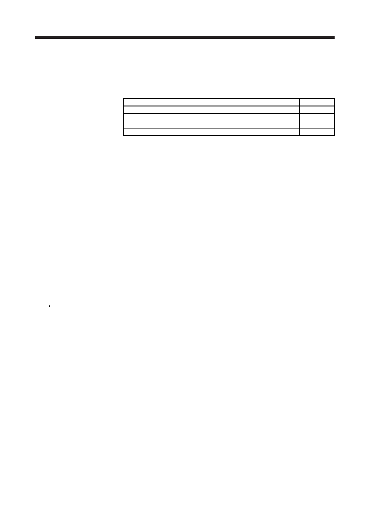
App. 5.1 Contents of the package
Open packing, and confirm the content of packing.
Contents Quantity
MR-J3-D05 Safety logic unit 1
Connector for CN9 1-1871940-4 (TE Connectivity) 1
Connector for CN10 1-1871940-8 (TE Connectivity) 1
MR-J3-D05 Safety Logic Unit Installation Guide 1
App. 5.2 Terms related to safety
App. 5.2.1 Stop function for IEC/EN 61800-5-2
(1) STO function (Refer to IEC/EN 61800-5-2:2016 4.2.2.2 STO.)
This function is integrated into the MR-J4 series servo amplifiers.
The STO function shuts down energy to servo motors, thus removing torque. This function electronically
cuts off power supply in servo amplifiers for MR-J4 series servo amplifiers.
The purpose of this function is as follows.
1) Uncontrolled stop according to stop category 0 of IEC/EN 60204-1
2) Preventing unexpected start-up
(2) SS1 function (Refer to IEC/EN 61800-5-2:2016 4.2.2.3C Safe stop 1 temporal delay.)
SS1 is a function which initiates the STO function when the previously set delay time has passed after
the servo motor starts decelerating. The delay time can be set with MR-J3-D05.
The purpose of this function is as follows. This function is available by using an MR-J4 series servo
amplifier with MR-J3-D05.
Controlled stop according to stop category 1 of IEC/EN 60204-1
App. 5.2.2 Emergency operation for IEC/EN 60204-1
(1) Emergency stop (Refer to IEC/EN 60204-1:2016 9.2.5.4.2 Emergency Stop.)
Emergency stop must override all other functions and actuation in all operation modes. Power to the
machine driving part which may cause a hazardous state must be either removed immediately (stop
category 0) or must be controlled to stop such hazardous state as soon as possible (stop category 1).
Restart must not be allowed even after the cause of the emergency state has been removed.
(2) Emergency shut-off (Refer to IEC/EN 60204-1:2016 9.2.5.4.3 Emergency Switching OFF.)
Removal of input power to driving device to remove electrical risk and to meet above mentioned safety
standards.
APPENDIX
App. - 6
App. 5.3 Cautions
The following basic safety notes must be read carefully and fully in order to prevent injury to persons or
damage to property.
Only qualified personnel are authorized to install, start-up, repair or service the machines in which these
components are installed.
They must be familiar with all applicable local regulations and laws in which machines with these
components are installed, particularly the standards mentioned in this user's manual and the requirements
described in ISO/EN ISO 13849-1:2015, EN IEC 62061, EN 61508, IEC/EN 61800-5-2, and IEC/EN 60204-
1.
The staff responsible for this work must be given express permission from the company to perform start-up,
programming, configuration, and maintenance of the machine in accordance with the safety standards.
WARNING
Improper installation of the safety related components or systems may cause
improper operation in which safety is not assured, and may result in severe
injuries or even death.
Protective Measures
As described in IEC/EN 61800-5-2, the Safe Torque Off (STO) function only prevents the servo amplifier
from supplying energy to the servo motor. Therefore, if an external force acts upon the drive axis,
additional safety measures, such as brakes or counter-weights must be used.
App. 5.4 Residual risk
Machine manufacturers are responsible for all risk evaluations and all associated residual risks. Below are
residual risks associated with the STO/EMG function. Mitsubishi Electric is not liable for any damages or
injuries caused by the residual risks.
(1) The SS1 function only guarantees the delay time before STO/EMG is engaged. Proper setting of this
delay time is the full responsibility of the company and/or individuals responsible for installation and
commissioning of the safety related system. The system, as a whole, must pass safety standards
certification.
(2) When the SS1 delay time is shorter than the required servo motor deceleration time, if the forced stop
function is malfunctioning, or if STO/EMG is engaged while the servo motor is still rotating; the servo
motor will stop with the dynamic brake or freewheeling.
(3) For proper installation, wiring, and adjustment, thoroughly read the installation guide of each individual
safety related component.
(4) Be sure that all safety related switches, relays, sensors, etc., meet the required safety standards.
A Certification Body has confirmed that the Mitsubishi Electric safety-related components mentioned in
this manual meet ISO/EN ISO 13849-1:2015 Category 3, PL d, EN IEC 62061, and EN 61508 SIL 2.
(5) Safety is not assured until safety-related components of the system are completely installed or adjusted.
(6) When replacing a servo amplifier etc. or MR-J3-D05, confirm that the new equipment is exactly the same
as those being replaced. Once installed, be sure to verify the performance of the functions before
commissioning the system.