sh030106u.pdf - 第174页
5. PARAMETE RS 5 - 29 No. Sym bol Name and function Initial value [unit] Setting range PB30 PG2B Position loop gain after gain switching Set the position loop gai n when the gain switchi ng is enabled. When you set a val…
5. PARAMETERS
5 - 28
No. Symbol Name and function
Initial
value
[unit]
Setting
range
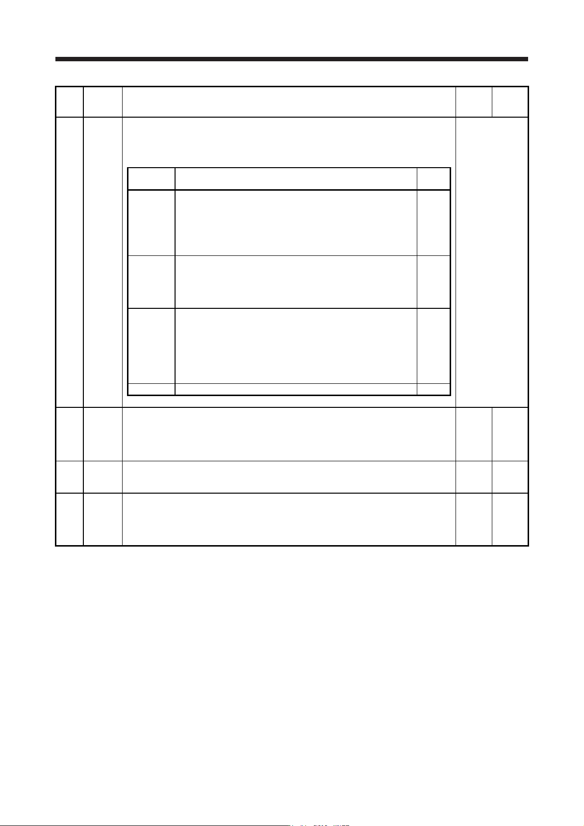
PB26 *CDP Gain switching function
Select the gain switching condition.
Set conditions to enable the gain switching values set in [Pr. PB29] to [Pr. PB36] and [Pr.
PB56] to [Pr. PB60].
Refer to the
"Name and
function" column.
Setting
digit
Explanation
Initial
value
_ _ _ x Gain switching selection
0: Disabled
1: Control command from controller is enabled
2: Command frequency
3: Droop pulses
4: Servo motor speed/linear servo motor speed
0h
_ _ x _ Gain switching condition selection
0: Gain after switching is enabled with gain switching condition or
more
1: Gain after switching is enabled with gain switching condition or
less
0h
_ x _ _ Gain switching time constant disabling condition selection
0: Switching time constant enabled
1: Switching time constant disabled
2: Return time constant disabled
Refer to section 7.2.4 for details.
This parameter is used by servo amplifier with software version B4
or later.
0h
x _ _ _ For manufacturer setting 0h
PB27 CDL Gain switching condition
This is used to set the value of gain switching (command frequency, droop pulses, and servo
motor speed/linear servo motor speed) selected in [Pr. PB26].
The set value unit differs depending on the switching condition item. (Refer to section 7.2.3.)
The unit "r/min" will be "mm/s" for linear servo motors.
10
[kpulse/s]
/[pulse]
/[r/min]
0 to
65535
PB28 CDT Gain switching time constant
This is used to set the time constant until the gains switch in response to the conditions set in
[Pr. PB26] and [Pr. PB27].
1
[ms]
0 to 100
PB29 GD2B Load to motor inertia ratio/load to motor mass ratio after gain switching
This is used to set the load to motor inertia ratio/load to motor mass ratio for when gain
switching is enabled.
This parameter is enabled only when you select "Manual mode (_ _ _ 3)" of "Gain adjustment
mode selection" in [Pr. PA08].
7.00
[Multiplier]
0.00 to
300.00
5. PARAMETERS
5 - 29
No. Symbol Name and function
Initial
value
[unit]
Setting
range
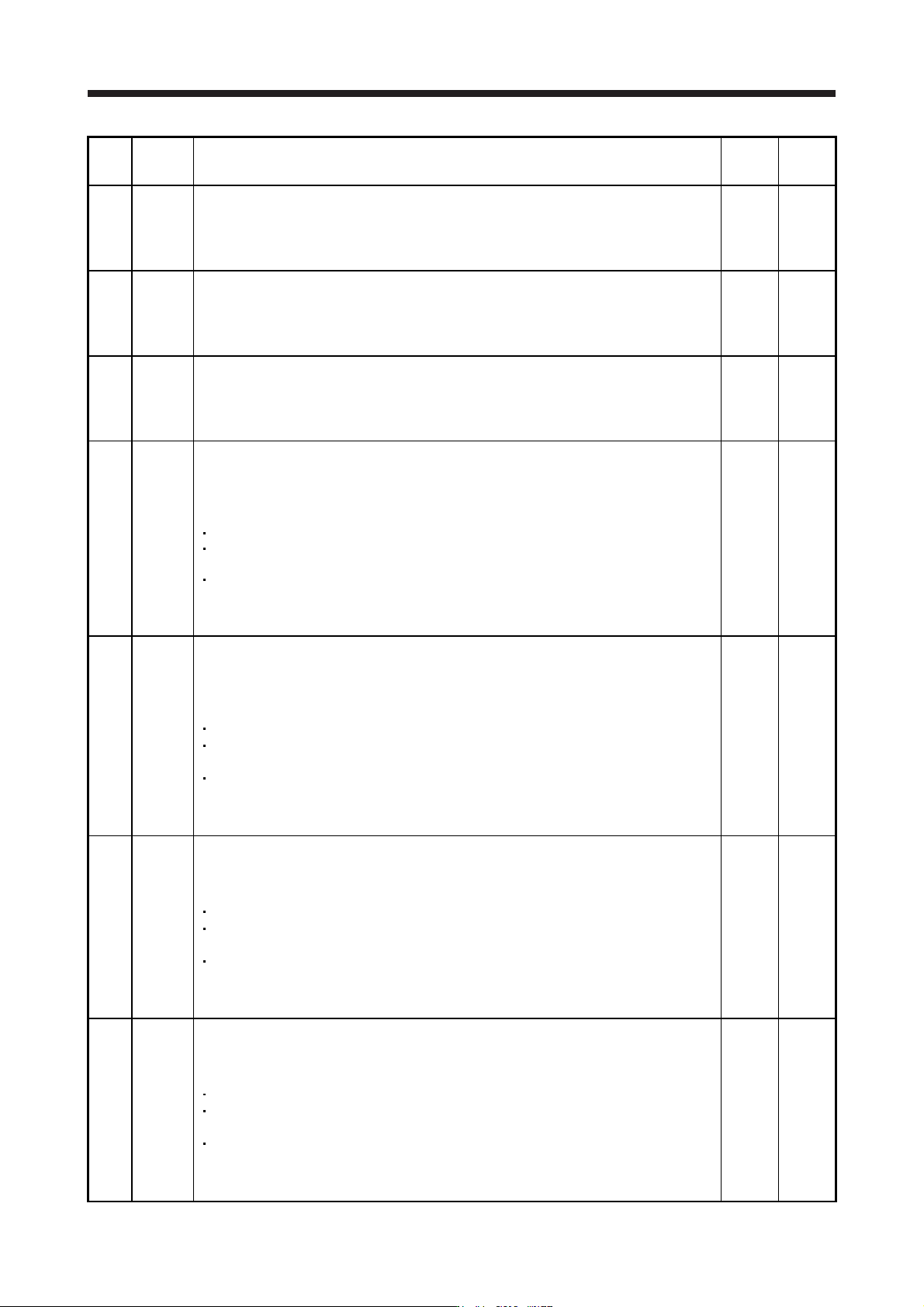
PB30 PG2B
Position loop gain after gain switching
Set the position loop gain when the gain switching is enabled.
When you set a value less than 1.0 rad/s, the value will be the same as [Pr. PB08].
This parameter is enabled only when you select "Manual mode (_ _ _ 3)" of "Gain adjustment
mode selection" in [Pr. PA08].
0.0
[rad/s]
0.0 to
2000.0
PB31 VG2B
Speed loop gain after gain switching
Set the speed loop gain when the gain switching is enabled.
When you set a value less than 20 rad/s, the value will be the same as [Pr. PB09].
This parameter is enabled only when you select "Manual mode (_ _ _ 3)" of "Gain adjustment
mode selection" in [Pr. PA08].
0
[rad/s]
0 to
65535
PB32 VICB
Speed integral compensation after gain switching
Set the speed integral compensation when the gain changing is enabled.
When you set a value less than 0.1 ms, the value will be the same as [Pr. PB10].
This parameter is enabled only when you select "Manual mode (_ _ _ 3)" of "Gain adjustment
mode selection" in [Pr. PA08].
0.0
[ms]
0.0 to
5000.0
PB33 VRF11B
Vibration suppression control 1 - Vibration frequency after gain switching
Set the vibration frequency of the vibration suppression control 1 for when the gain switching
is enabled.
When you set a value less than 0.1 Hz, the value will be the same as [Pr. PB19].
This parameter is enabled only when the following conditions are fulfilled.
"Gain adjustment mode selection" in [Pr. PA08] is "Manual mode (_ _ _ 3)".
"Vibration suppression control 1 tuning mode selection" in [Pr. PB02] is "Manual setting (_ _
_ 2)".
"Gain switching selection" in [Pr. PB26] is "Control command from controller is enabled (_ _
_ 1)".
Switching during driving may cause a shock. Be sure to switch them after the servo motor or
linear servo motor stops.
0.0
[Hz]
0.0 to
300.0
PB34 VRF12B Vibration suppression control 1 - Resonance frequency after gain switching
Set the resonance frequency for vibration suppression control 1 when the gain switching is
enabled.
When you set a value less than 0.1 Hz, the value will be the same as [Pr. PB20].
This parameter will be enabled only when the following conditions are fulfilled.
"Gain adjustment mode selection" in [Pr. PA08] is "Manual mode (_ _ _ 3)".
"Vibration suppression control 1 tuning mode selection" in [Pr. PB02] is "Manual setting (_ _
_ 2)".
"Gain switching selection" in [Pr. PB26] is "Control command from controller is enabled (_ _
_ 1)".
Switching during driving may cause a shock. Be sure to switch them after the servo motor or
linear servo motor stops.
0.0
[Hz]
0.0 to
300.0
PB35 VRF13B Vibration suppression control 1 - Vibration frequency damping after gain switching
Set a damping of the vibration frequency for vibration suppression control 1 when the gain
switching is enabled.
This parameter will be enabled only when the following conditions are fulfilled.
"Gain adjustment mode selection" in [Pr. PA08] is "Manual mode (_ _ _ 3)".
"Vibration suppression control 1 tuning mode selection" in [Pr. PB02] is "Manual setting (_ _
_ 2)".
"Gain switching selection" in [Pr. PB26] is "Control command from controller is enabled (_ _
_ 1)".
Switching during driving may cause a shock. Be sure to switch them after the servo motor or
linear servo motor stops.
0.00 0.00
to
0.30
PB36 VRF14B Vibration suppression control 1 - Resonance frequency damping after gain switching
Set a damping of the resonance frequency for vibration suppression control 1 when the gain
switching is enabled.
This parameter will be enabled only when the following conditions are fulfilled.
"Gain adjustment mode selection" in [Pr. PA08] is "Manual mode (_ _ _ 3)".
"Vibration suppression control 1 tuning mode selection" in [Pr. PB02] is "Manual setting (_ _
_ 2)".
"Gain switching selection" in [Pr. PB26] is "Control command from controller is enabled (_ _
_ 1)".
Switching during driving may cause a shock. Be sure to switch them after the servo motor or
linear servo motor stops.
0.00 0.00
to
0.30
5. PARAMETERS
5 - 30
No. Symbol Name and function
Initial
value
[unit]
Setting
range
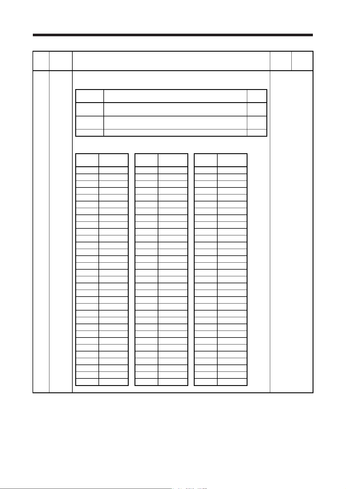
PB45 CNHF Command notch filter
Set the command notch filter.
Refer to the
"Name and
function" column.
Setting
digit
Explanation
Initial
value
_ _ x x Command notch filter setting frequency selection
Refer to table 5.5 for the relation of setting values to frequency.
00h
_ x _ _ Notch depth selection
Refer to table 5.6 for details.
0h
x _ _ _ For manufacturer setting 0h
Table 5.5 Command notch filter setting frequency selection
Setting
value
Frequency
[Hz]
Setting
value
Frequency
[Hz]
Setting
value
Frequency
[Hz]
_ _ 0 0 Disabled _ _ 2 0 70 _ _ 4 0 17.6
_ _ 0 1 2250 _ _ 2 1 66 _ _ 4 1 16.5
_ _ 0 2 1125 _ _ 2 2 62 _ _ 4 2 15.6
_ _ 0 3 750 _ _ 2 3 59 _ _ 4 3 14.8
_ _ 0 4 562 _ _ 2 4 56 _ _ 4 4 14.1
_ _ 0 5 450 _ _ 2 5 53 _ _ 4 5 13.4
_ _ 0 6 375 _ _ 2 6 51 _ _ 4 6 12.8
_ _ 0 7 321 _ _ 2 7 48 _ _ 4 7 12.2
_ _ 0 8 281 _ _ 2 8 46 _ _ 4 8 11.7
_ _ 0 9 250 _ _ 2 9 45 _ _ 4 9 11.3
_ _ 0 A 225 _ _ 2 A 43 _ _ 4 A 10.8
_ _ 0 B 204 _ _ 2 B 41 _ _ 4 B 10.4
_ _ 0 C 187 _ _ 2 C 40 _ _ 4 C 10
_ _ 0 D 173 _ _ 2 D 38 _ _ 4 D 9.7
_ _ 0 E 160 _ _ 2 E 37 _ _ 4 E 9.4
_ _ 0 F 150 _ _ 2 F 36 _ _ 4 F 9.1
_ _ 1 0 140 _ _ 3 0 35.2 _ _ 5 0 8.8
_ _ 1 1 132 _ _ 3 1 33.1 _ _ 5 1 8.3
_ _ 1 2 125 _ _ 3 2 31.3 _ _ 5 2 7.8
_ _ 1 3 118 _ _ 3 3 29.6 _ _ 5 3 7.4
_ _ 1 4 112 _ _ 3 4 28.1 _ _ 5 4 7.0
_ _ 1 5 107 _ _ 3 5 26.8 _ _ 5 5 6.7
_ _ 1 6 102 _ _ 3 6 25.6 _ _ 5 6 6.4
_ _ 1 7 97 _ _ 3 7 24.5 _ _ 5 7 6.1
_ _ 1 8 93 _ _ 3 8 23.4 _ _ 5 8 5.9
_ _ 1 9 90 _ _ 3 9 22.5 _ _ 5 9 5.6
_ _ 1 A 86 _ _ 3 A 21.6 _ _ 5 A 5.4
_ _ 1 B 83 _ _ 3 B 20.8 _ _ 5 B 5.2
_ _ 1 C 80 _ _ 3 C 20.1 _ _ 5 C 5.0
_ _ 1 D 77 _ _ 3 D 19.4 _ _ 5 D 4.9
_ _ 1 E 75 _ _ 3 E 18.8 _ _ 5 E 4.7
_ _ 1 F 72 _ _ 3 F 18.2 _ _ 5 F 4.5