sh030106u.pdf - 第651页
APPENDIX App. - 20 App. 5.1 2 Dimens ions [Unit: mm] Rating plate 5 182 5 192 5 FG 9.75 5 mounting hole 12 168 6 86 80 2-M4 screw Approx. 22.5 9.75 Approx. 192 Approx. 5 Approx. 5 182 Approx. 80 Mounting hole process dra…
APPENDIX
App. - 19
App. 5.11 Troubleshooting
When power is not supplied or FAULT LED turns on, refer the following table and take the appropriate
action.
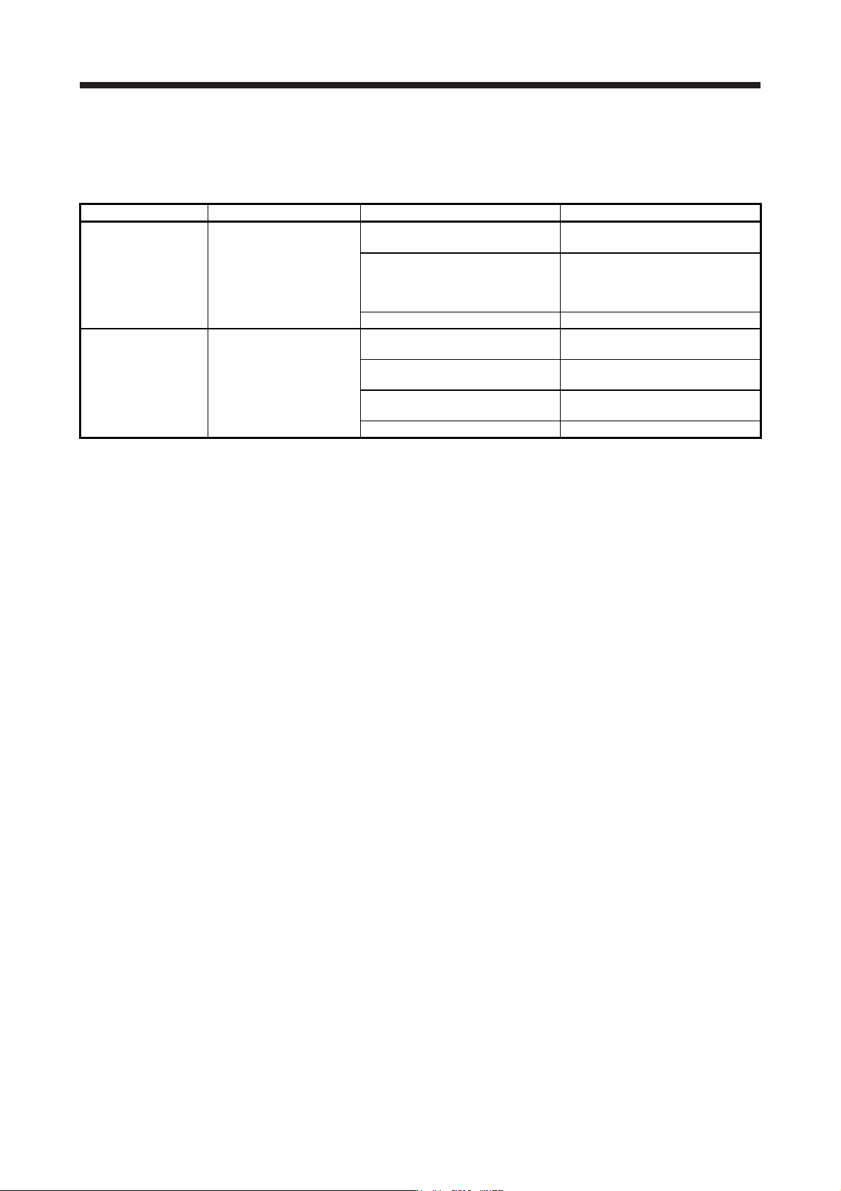
Event Definition Cause Action
Power is not supplied.
Power LED does not turn on
although power is supplied.
1. 24 V DC power supply is
malfunctioning.
Replace the 24 V DC power supply.
2. Wires between MR-J3-D05 and 24
V DC power supply are
disconnected or are in contact with
other wires.
Check the wiring.
3. MR-J3-D05 is malfunctioning. Replace the MR-J3-D05.
FAULT LED is on.
FAULT LED of A-axis or B-
axis is on, and will not turn
off.
1. The delay time settings are not
matched.
Check the settings of the rotary
switch.
2. Switch input error
Check the wiring or sequence of the
input signals.
3. TOF signal error
Check the connection with the servo
amplifier.
4. MR-J3-D05 is malfunctioning. Replace the MR-J3-D05.
APPENDIX
App. - 20
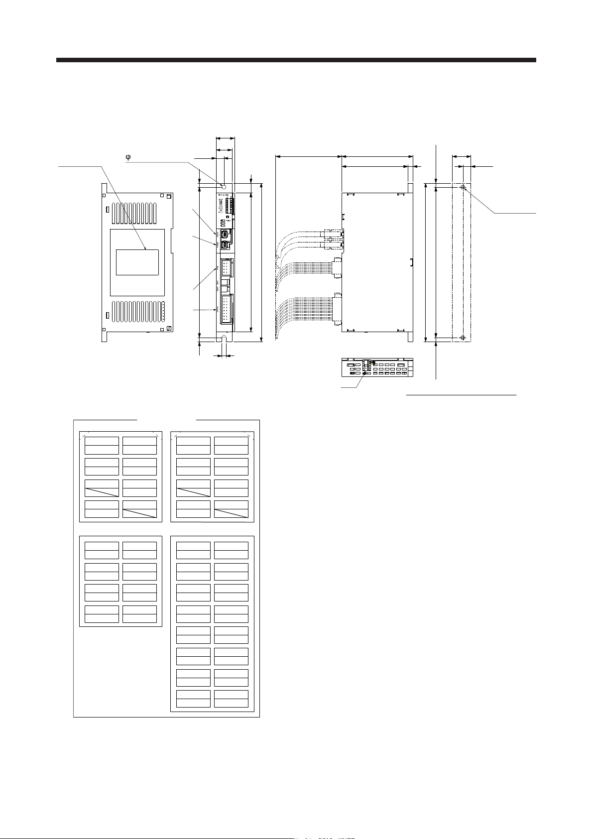
App. 5.12 Dimensions
[Unit: mm]
Rating plate
51825
192
5
FG
9.75
5 mounting hole
12168
6
86
80
2-M4 screw
Approx. 22.5
9.75
Approx. 192
Approx. 5Approx. 5
182
Approx. 80
Mounting hole process drawing
19.5
22.5
CN8ACN8BCN9CN10
78 78
TOF2A TOF1A TOF2B TOF1B
56 56
STO2A- STO2A+ STO2B- STO2B+
34 34
STO1A+ STO1B+
12 12
STO1A- STO1B-
1A 1B 1A 1B
SDI1A+ SDI1A- SRESA+ SRESA-
2A 2B 2A 2B
SDI1B+ SDI1B- SRESB+ SRESB-
3A 3B 3A 3B
SDO1B+ SDO1B- SDI2A+ SDI2A-
4A 4B 4A 4B
SDO1A+ SDO1A- SDI2B+ SDI2B-
5A 5B
SDO2B+ SDO2B-
6A 6B
SDO2A+ SDO2A-
7A 7B
+24 V 0 V
8A 8B
TOFA TOFB
CN8A CN8B
Pin assignment
CN9 CN10
Mounting screw
Screw size: M4
Tightening torque: 1.2 N•m
Mass: 0.2 [kg]
APPENDIX
App. - 21
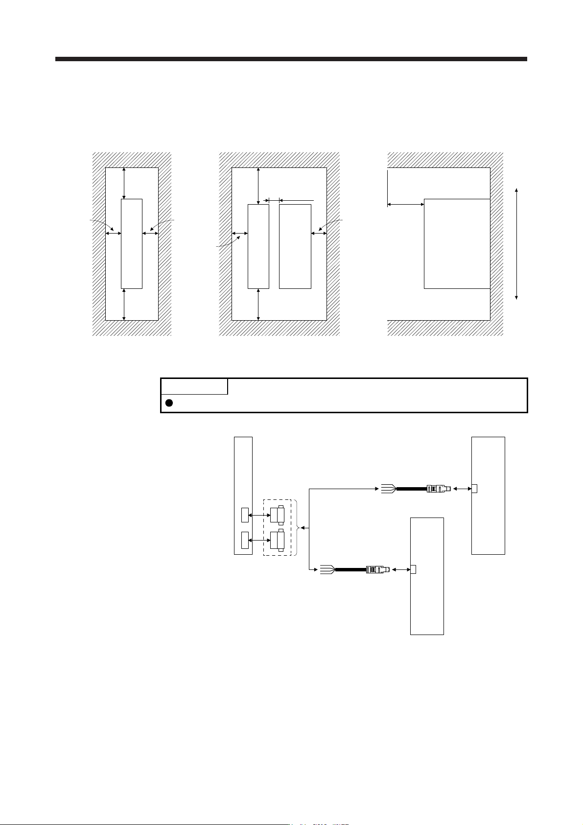
App. 5.13 Installation
Follow the instructions in this section and install MR-J3-D05 in the specified direction. Leave clearances
between MR-J3-D05 and other equipment including the cabinet.
Cabine
t
10 mm or
longer
80 mm or longer
for wiring
30 mm or
longer
10 mm or
longer
Top
Bottom
40 mm or
longer
40 mm or
longer
40 mm or
longer
30 mm or
longer
100 mm or longer
10 mm or
longer
Cabine
t
Cabine
t
MR-J3-D05
MR-J3-D05
MR-J3-D05
Other device
App. 5.14 Combinations of cable/connector
POINT
MR-D05UDL_M (STO cable) for MR-J3 series cannot be used.
MR-J3-D05
attachment
connector
CN9
CN10
MR-J3-D05
2)
2)
CN8
MR-J4_B_(-RJ)
MR-J4_B_(-RJ)
1)
CN8