sh030106u.pdf - 第639页
APPENDIX App. - 8 App. 5.7 Functions and configuration App. 5.7.1 Summary MR-J3-D05 has two syste ms in which the each system has SS1 function (delay time) and output of STO function. App. 5.7.2 Specifications Safety log…
APPENDIX
App. - 7
(7) Perform all risk assessments and safety level certification to the machine or the system as a whole.
It is recommended that a Certification Body final safety certification of the system be used.
(8) To prevent accumulation of multiple malfunctions, perform a malfunction check at regular intervals as
deemed necessary by the applicable safety standard. Regardless of the system safety level, malfunction
checks should be performed at least once per year.
(9) If the upper and lower power modules in the servo amplifier are shorted and damaged simultaneously,
the servo motor may make a half revolution at a maximum. For a linear servo motor, the primary side will
move a distance of pole pitch.
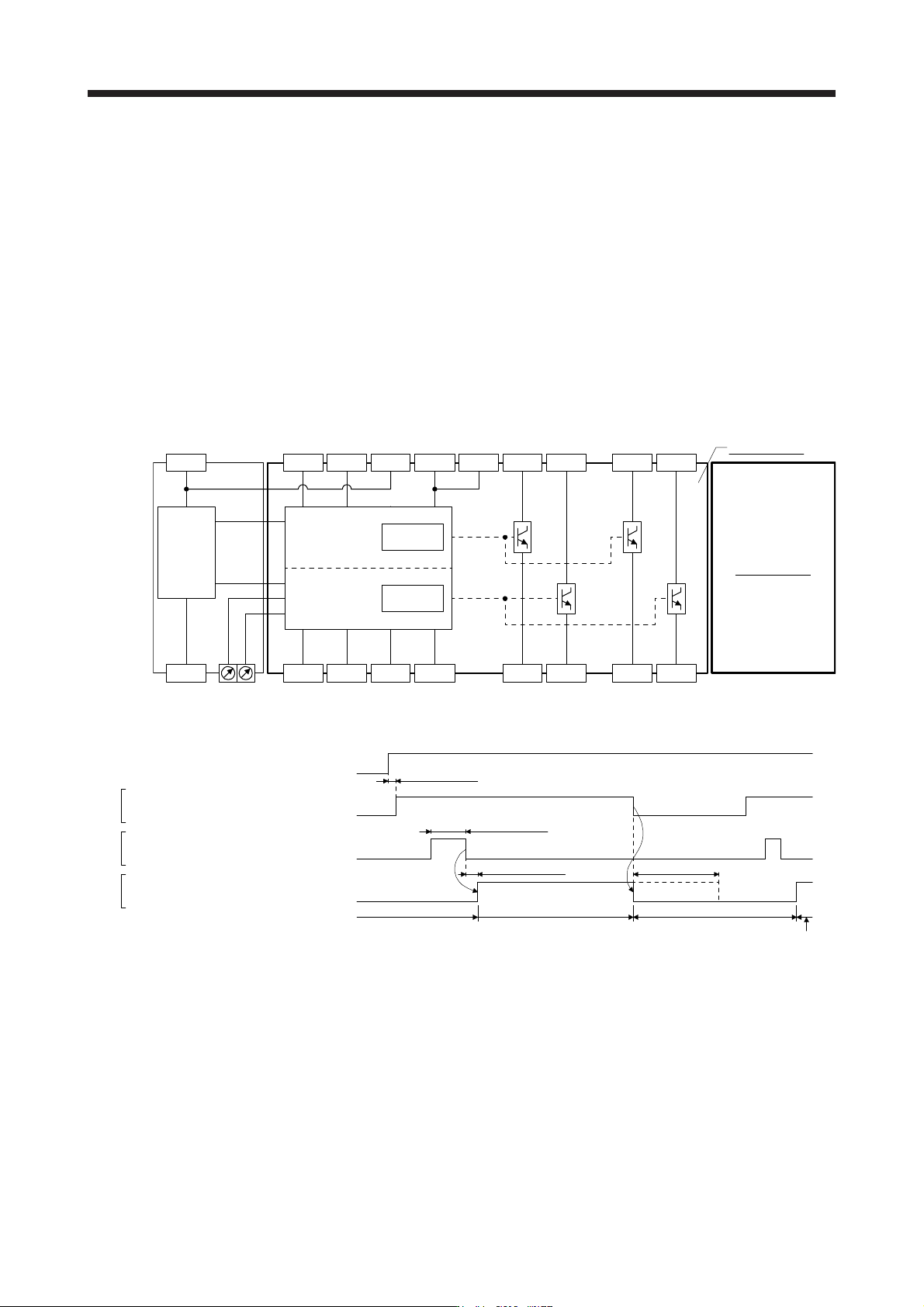
App. 5.5 Block diagram and timing chart
(1) Function block diagram
SDI1A- SDI2A- SDI1B- SDI2B- STO1A- STO2A- SDO1A- SDO2A-
SRESA+ SRESA- TOF1A TOF2A STO1A+ STO2A+ SDO1A+ SDO2A+TOFA
0V
+24V
DCDC
power
Safety logic
TIMER1
TIMER2
A
-axis circui
t
SW1 SW2
B-axis circuit
(2) Operation sequence
A-axis shutdown 1 and 2
B-axis shutdown 1 and 2
Energizing (close)
Shut-off (open)
Release (close)
Normal (open)
Normal (close)
Shut-off (open)
A-axis EMG start/reset
B-axis EMG start/reset
A-axis STO state 1 and 2
B-axis STO state 1 and 2
10 ms or shorter Shut off delay (SW1 and SW2) (Note)
STO status
Control enabled
STO status
50 ms or longer
SDI
SRES
STO
15 ms or longer
Power supply
Control enabled
Note. Refer to App. 5.10.
App. 5.6 Maintenance and disposal
MR-J3-D05 is equipped with LED displays to check errors for maintenance.
Please dispose this unit according to your local laws and regulations.
APPENDIX
App. - 8
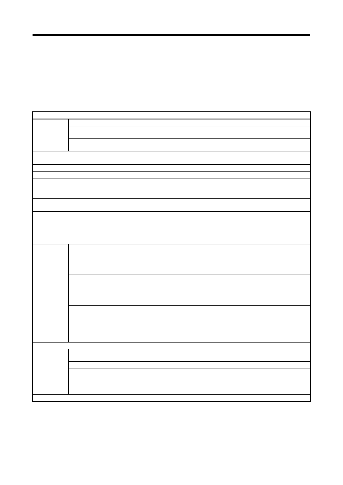
App. 5.7 Functions and configuration
App. 5.7.1 Summary
MR-J3-D05 has two systems in which the each system has SS1 function (delay time) and output of STO
function.
App. 5.7.2 Specifications
Safety logic unit model MR-J3-D05
Control circuit
power supply
Voltage 24 V DC
Permissible
voltage fluctuation
24 V DC ± 10%
Power supply
capacity
[A] 0.5 (Note 1, 2)
Compatible system 2 systems (A-axis, B-axis independent)
Shut-off input 2 points (duplex wiring) SDI
_
: (source/sink compatible) (Note 3)
Shut-off release input 1 point (duplex wiring) SRES
_
: (source/sink compatible) (Note 3)
Feedback input 1 point (duplex wiring) TOF
_
: (source compatible) (Note 3)
Input type Photocoupler insulation, 24 V DC (external supply), internal limited resistance 5.4 kΩ
Shut-off output
4 points (duplex wiring)
STO
_
: (source compatible) (Note 3)
SDO
_
: (source/sink compatible) (Note 3)
Output method
Photocoupler insulation, open-collector type
Permissible current: 40 mA/1 output, Inrush current: 100 mA/1 output
Delay time setting
A-axis: Select from 0 s, 1.4 s, 2.8 s, 5.6 s, 9.8 s, or 30.8 s.
B-axis: Select from 0 s, 1.4 s, 2.8 s, 9.8 s, or 30.8 s.
Accuracy: ±2%
Functional safety
STO, SS1 (IEC/EN 61800-5-2)
EMG STOP, EMG OFF IEC/EN 60204-1)
Safety
performance
Standard ISO 13849-1:2015 Category 3 PL d, EN IEC 62061, EN 61508 SIL2, IEC 61800-5-2
Response
performance (when
delay time is set to
0 s) (Note 4)
10 ms or less (STO input off → shut-off output off)
Mean time to
dangerous failure
(MTTFd)
MTTFd ≥ 100 [years] (516a)
Diagnosis
converge (DC avg)
DC = Medium, 93.1 [%]
Probability of
dangerous failures
per hour (PFH)
4.75 × 10
-9
[1/h]
Global
standards
CE marking
LVD: EN 61800-5-1
EMC: EN 61800-3
MD: EN ISO 13849-1:2015, EN 61800-5-2, EN IEC 62061
Structure Natural-cooling, open (IP rating: IP 00)
Environment
Ambient
temperature
0 °C to 55 °C (non-freezing), storage: -20 °C to 65 °C (non-freezing)
Ambient humidity 5 %RH to 90 %RH (non-condensing), storage: 5 %RH to 90 %RH (non-condensing)
Ambience Indoors (no direct sunlight), free from corrosive gas, flammable gas, oil mist, dust, and dirt
Altitude Max. 1000 m above sea level
Vibration
resistance
5.9 m/s
2
at 10 Hz to 55 Hz (directions of X, Y and Z axes)
Mass [kg] 0.2 (including CN9 and CN10 connectors)
Note 1. Inrush current of approximately 1.5 A flows instantaneously when turning the control circuit power supply on. Select an
appropriate capacity of power supply considering the inrush current.
2. Power-on duration of the safety logic unit is 100,000 times.
3.
_
: in signal name indicates a number or axis name.
4. For the test pulse input, contact your local sales office.
APPENDIX
App. - 9
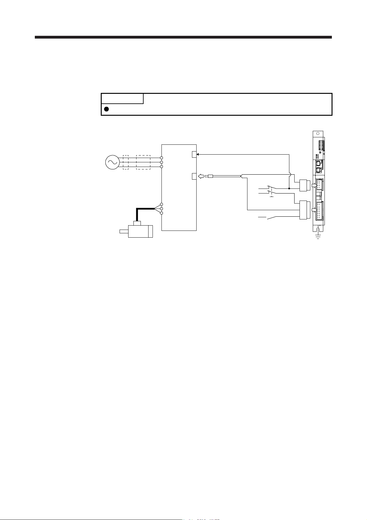
App. 5.7.3 When using MR-J3-D05 with an MR-J4 series servo amplifier
(1) System configuration diagram
The following shows the connection targets of the STO switch and STO release switch.
POINT
MR-D05UDL_M (STO cable) for MR-J3 series cannot be used.
MR-J3-D05
FG
STO switch
STO release switch
Magnetic
contactor
MCCB
Power
supply
Servo motor
MR-J4_B_(-RJ)
STO cable
MR-D05UDL3M-B
CN9
CN10
CN8
CN3
L1
L2
L3
U
V
W
EM2 (Forced stop 2)