sh030106u.pdf - 第528页
16. FULLY CLOSE D LOOP SYSTEM 16 - 3 16.1.2 Selecting proc edure of control mode (1) Control mode configuration In this servo, a semi closed loop syste m or fully closed loop s ystem can be sel ected as a control system.…

16. FULLY CLOSED LOOP SYSTEM
16 - 2
The following table shows the functions of each control mode.
Control Description
Semi closed loop control
Feature Position is controlled according to the servo motor-side data.
Advantage
Since this control is insusceptible to machine influence (such as machine resonance),
the gains of the servo amplifier can be raised and the settling time shortened.
Disadvantage
If the servo motor side is at a stop, the side may be vibrating or the load-side accuracy
not obtained.
Dual feedback control
Feature Position is controlled according to the servo motor-side data and load-side data.
Advantage
Control is performed according to the servo motor-side data during operation, and
according to the load side-data at a stop in sequence to raise the gains during
operation and shorten the settling time. A stop is made with the load-side accuracy.
Fully closed loop control
Feature Position is controlled according to the load-side data.
Advantage The load-side accuracy is obtained not only at a stop but also during operation.
Disadvantage
Since this control is susceptible to machine resonance or other influences, the gains
of the servo amplifier may not rise.
16. FULLY CLOSED LOOP SYSTEM
16 - 3
16.1.2 Selecting procedure of control mode
(1) Control mode configuration
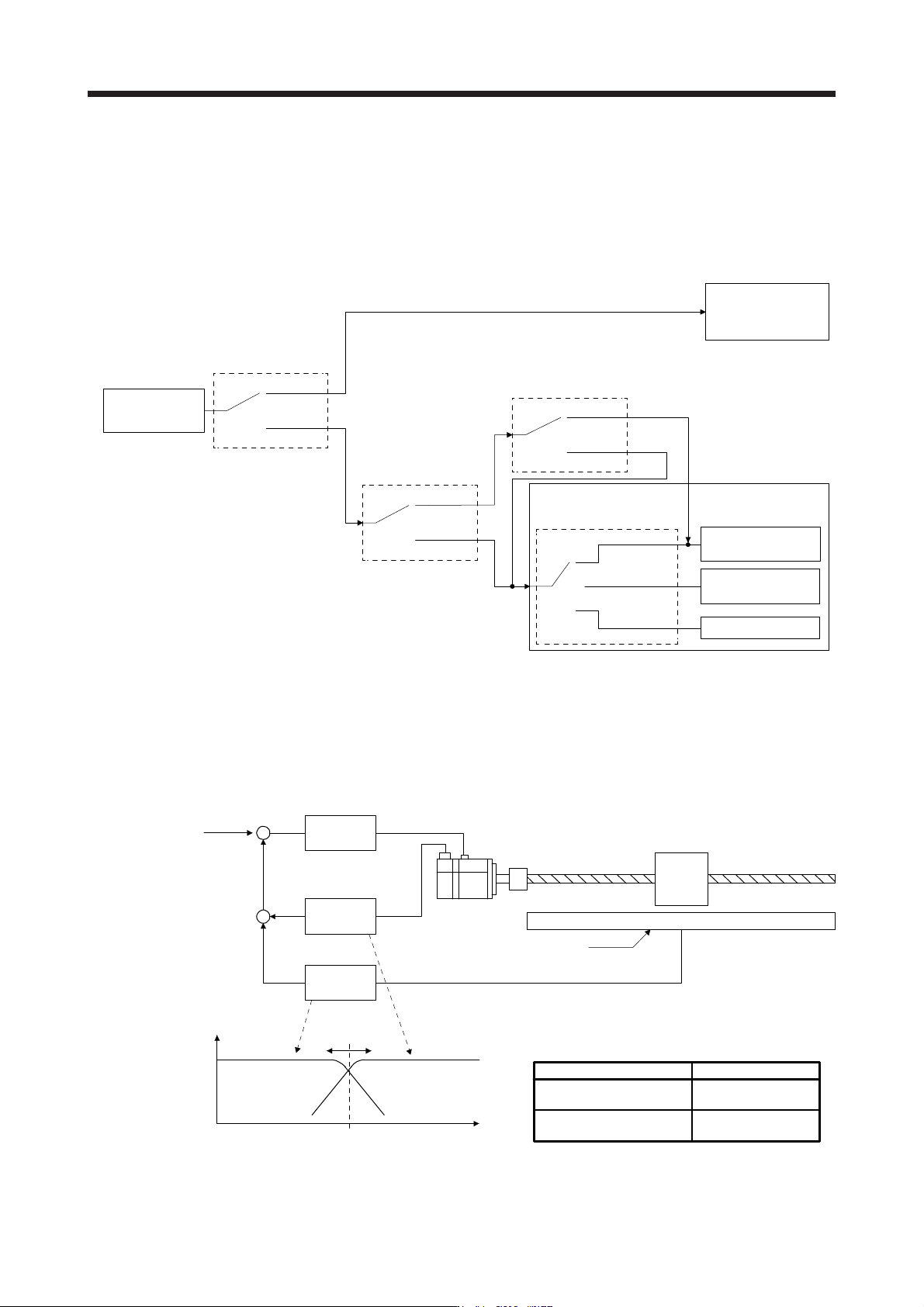
In this servo, a semi closed loop system or fully closed loop system can be selected as a control system.
In addition, on the fully closed loop system, the semi closed loop control, fully closed loop control and
dual feedback control can be selected by the [Pr. PE08] settings.
"4500"
"1 to 4499"
"0"
Fully closed loop
function selection 1
([Pr. PE01])
Operation mode selection
([Pr. PA01])
"_ _ _ 1"
"_ _ _ 0"
Fully closed
loop control
Semi closed
loop control
(Note 1)
"_ _ 0 _"
Servo amplifier
"_ _ 1 _"
(Refer to section 16.3.1 (2) (a))
Semi closed/fully closed switching command
(Refer to the controller user's manual.)
OFF
ON
(Refer to section 16.3.1 (2) (b))
Dual feedback
control
Semi closed
loop control
(Note 2)
Fully closed loop system
Fully closed loop
dual feedback filter
([Pr. PE08])
Semi closed loop system
Note 1. Use the servo motor encoder unit for the command unit. Use the servo motor-side information for the alarm determination.
2.
Use the load-side encoder information for the command unit. When [Pr. PE08 Fully closed loop dual feedback filter] is set to
"0", the load-side information is used for determining alarms such as error excessive.
When the semi closed/fully closed
switching command is turned off, the servo motor-side information is used for determining alarms such as error excessive.
(2) Dual feedback filter equivalent block diagram
A dual feedback filter equivalent block diagram on the dual feedback control is shown below.
Servo motor during a stop
(0 to ω)
Fully closed loop
control
In operation (ω or more)
Semi closed loop
control
Semi closed
loop control
Fully closed
loop control
+
+
+
-
Dual feedback filter
Servo motor
Linear encoder
Position
control unit
High-pass
filter
Low-pass
filter
ω (Note)
Frequency [rad/s]
Operation status
Control status
Note. "ω" (a dual feedback filter band) is set by [Pr. PE08].
16. FULLY CLOSED LOOP SYSTEM
16 - 4
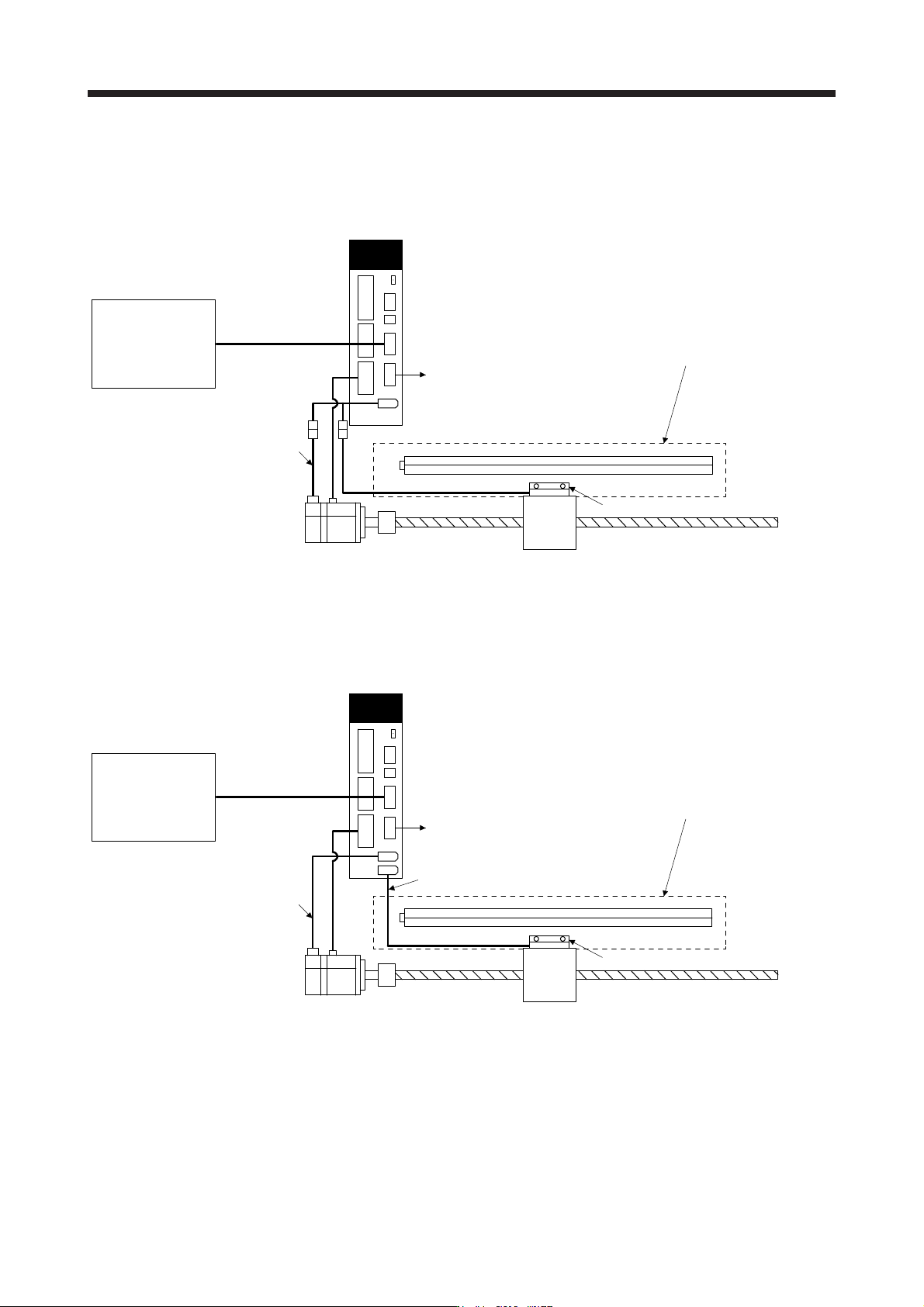
16.1.3 System configuration
(1) For a linear encoder
(a) MR-J4-_B_ servo amplifier
CN2
Servo amplifier
SSCNET III/H controller
SSCNET III/H
Position command
control signal
Table
To the next servo amplifier
(Note)
Two-wire type serial interface compatible linear encoder
Load-side encoder signal
Servo motor encoder signal
Linear encoder head
Servo motor
Note.
A
pplicable for the absolute position detection system when an absolute position linear encoder is used.
In that case, a batter
y
is not required.
(b) MR-J4-_B_-RJ servo amplifier
CN2
(Note)
A/B/Z-phase pulse train interface compatible linear encoder
or
two-wire/four-wire type serial interface compatible linear encoder
CN2L
(A/B/Z-phase pulse train interface
or serial interface)
Servo amplifier
SSCNET III/H controller
SSCNET III/H
Position command
control signal
Table
To the next servo amplifier
Load-side encoder signal
Servo motor encoder signal
Linear encoder head
Servo motor
Note.
A
pplicable for the absolute position detection system when an absolute position linear encoder is used.
In that case, a batter
y
is not required.