sh030106u.pdf - 第516页
15. USIN G A DI REC T DRIV E MOTOR 15 - 13 2) Specify the s etting v alue th at is a n approxi mately 70% of th e v alue set when [ AL. 50 Ov erload 1 ], [AL. 51 Ov erload 2], [AL. E1 O verload warn ing 1], an d [AL. EC …
15. USING A DIRECT DRIVE MOTOR
15 - 12
2) Execute the magnetic pole detection. (Refer to (3) (a) in this section.)
3) After the completion of the magnetic pole detection, change [Pr. PL01] to "_ _ _ 0" (Magnetic pole
detection disabled).
[Pr. PL01]
Magnetic pole detection disabled
0
After the magnetic pole detection, by turning on the Z-phase pulse in JOG operation and by
disabling the magnetic pole detection function with [Pr. PL01], the magnetic pole detection after
each power-on is not required.
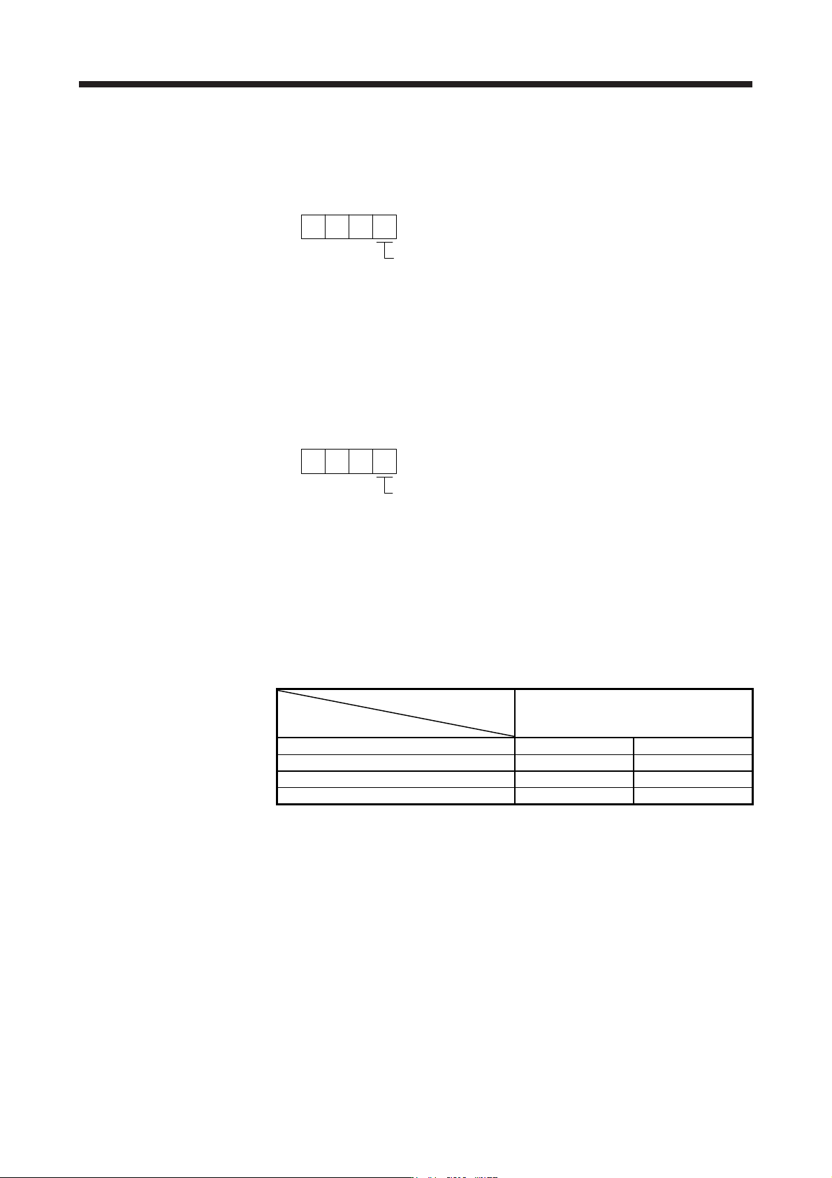
(4) Magnetic pole detection method setting
Set the magnetic pole detection method using the first digit of [Pr. PL08] (Magnetic pole detection
method selection).
[Pr. PL08]
Magnetic pole detection method selectio
n
0: Position detection method
4: Minute position detection method
(5) Setting of the magnetic pole detection voltage level by the position detection method
For the magnetic pole detection by the position detection method, set the voltage level with [Pr. PL09
Magnetic pole detection voltage level]. For the magnetic pole detection by the minute position detection
method, the voltage level setting is not required.
(a) Guideline of parameter settings
Set the parameters by referring to the following table.
[Pr. PL09] setting
(Guide value)
Servo status
Small ← Medium → Large
(10 or less (initial value) 50 or more)
Torques required for operation Small Large
Overload, overcurrent alarm Not frequently occurs Frequently occurs
Magnetic pole detection alarm Frequently occurs Not frequently occurs
Magnetic pole detection accuracy Low High
(b) Setting procedure
1) Perform the magnetic pole detection, and increase the setting value of [Pr. PL09 Magnetic pole
detection voltage level] until [AL. 50 Overload 1], [AL. 51 Overload 2], [AL. E1 Overload warning
1], and [AL. EC Overload warning 2] occur. Increase the setting value by five as a guide value.
When these alarms and warnings occur during the magnetic pole detection by using MR
Configurator2, the test operation of MR Configurator2 automatically completes and the servo-off
status is established.
15. USING A DIRECT DRIVE MOTOR
15 - 13
2) Specify the setting value that is an approximately 70% of the value set when [AL. 50 Overload 1],
[AL. 51 Overload 2], [AL. E1 Overload warning 1], and [AL. EC Overload warning 2] occurred as
the final setting value. However, if [AL. 27 Initial magnetic pole detection error] occurs with this
value, specify a value intermediate between the value set at [AL. 50 Overload 1], [AL. 51
Overload 2], [AL. E1 Overload warning 1], or [AL. EC Overload warning 2] and the value set at
the magnetic pole detection alarm as the final setting value.
3) Perform the magnetic pole detection again with the final setting value.
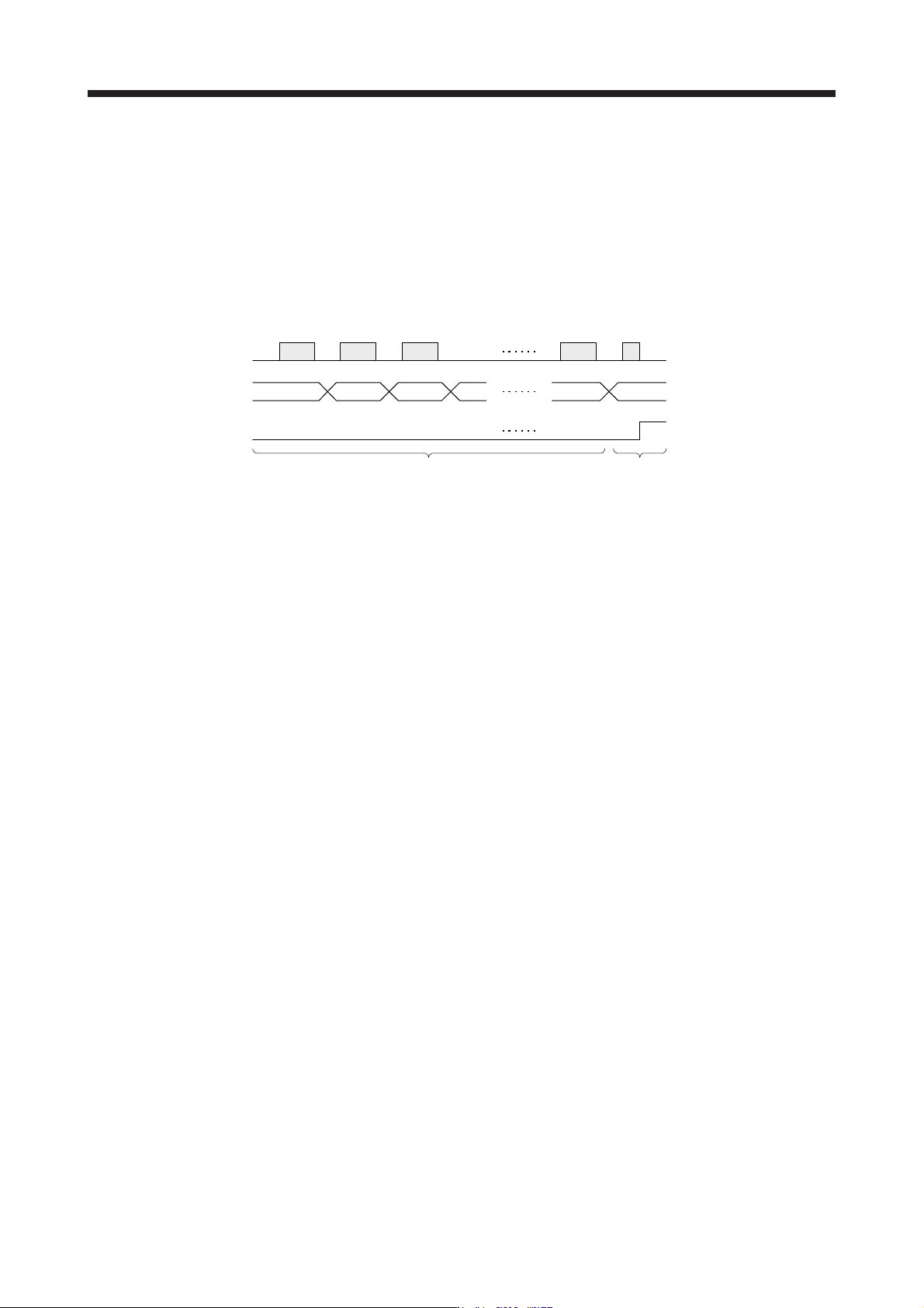
(c) Setting example
Existent
Non-existent
A
larm
Magnetic pole detection
[Pr. PL09] setting value
An alarm has occurred when the setting
value of [Pr. PL09] is set to "70".
While increasing the setting value of [Pr. PL09], carry out the
magnetic pole detection repeatedly.
30 35 40 45 65 70
In this example, the final setting value of [Pr. PL09] is 49 (Setting value at the alarm occurrence = 70
× 0.7).

15. USING A DIRECT DRIVE MOTOR
15 - 14
15.3.3 Operation from controller
To configure the absolute position detection system by using the direct drive motor, the battery and the
absolute position storage unit MR-BTAS01 are required.
(1) Operation method
For the incremental system, the magnetic pole detection is automatically performed at the first servo-on
after the power-on. For this reason, when performing the positioning operation, create the sequence
which surely confirms the servo-on status as the inter lock condition of the positioning command.
Also, some parameter settings and the home position return differ according to the controller type.
(2) Servo system controller setting
The following parameters will be enabled by cycling the servo amplifier power after the controller writes
the parameters to the servo amplifier.
Setting item
Setting
Motion controller
R_MTCPU/Q17_DSCPU
Simple motion module
RD77MS_/QD77MS_ /
LD77MS_
Parameter
Amplifier setting MR-J4-B DD
Motor setting Automatic setting
No.
(Note)
Symbol
Name
Initial
value
PA01 **STY Operation mode 1000h 1060h
PC01 *ERZ Error excessive alarm level 0
Set the items as required.
PC03 *ENRS Encoder output pulse selection 0000h
PL01 **LIT1
Linear servo motor/DD motor function
selection 1
0301h
PL04 *LIT2
Linear servo motor/DD motor function
selection 2
0003h
PL05 LB1 Position deviation error detection level 0
PL06 LB2 Speed deviation error detection level 0
PL07 LB3
Torque/thrust deviation error detection
level
100
PL08 *LIT3
Linear servo motor/DD motor function
selection 3
0010h
PL09 LPWM Magnetic pole detection voltage level 30
PL17 LTSTS
Magnetic pole detection - Minute
position detection method - Function
selection
0000h
PL18 IDLV
Magnetic pole detection - Minute
position detection method -
Identification signal amplitude
0
Note. The parameter whose symbol is preceded by * is enabled with the following conditions.
* : After setting the parameter, power off and on the servo amplifier or reset the controller.
**: After settin
g
the parameter, power off and on the servo amplifier.