sh030106u.pdf - 第648页
APPENDIX App. - 17 (3) Connector insertion Insert the connec tor all t he way straigh t until you hear or fee l c licki ng. When r emov ing the con nector, depress the lock part comp letely before pull ing out. If t he c…
APPENDIX
App. - 16
(b) Using a screwdriver
To avoid damaging housings and springs when wiring with screwdriver, do not put excessive force.
Be cautious when connecting.
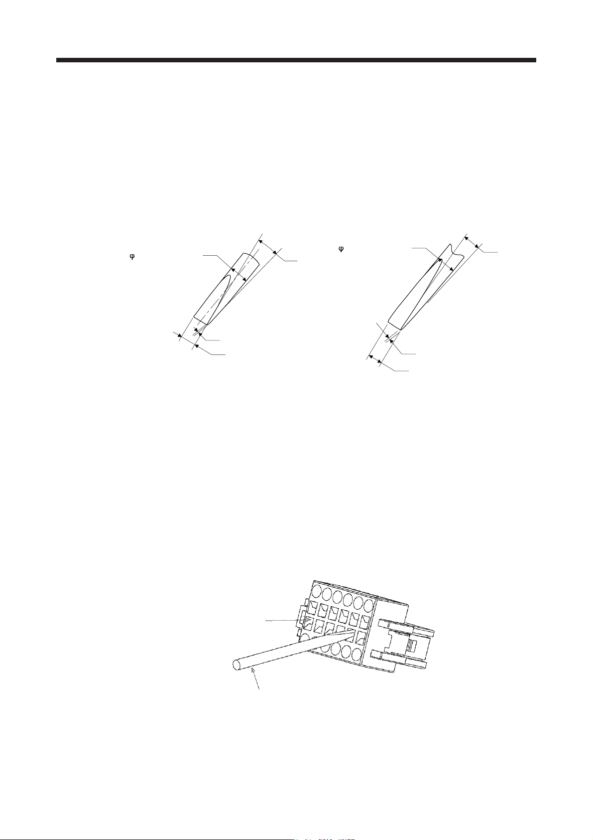
1) Adjusting screw driver
Diameter: 2.3 mm ± 0.05 mm
Length: 120 mm or less
Width: 2.3 mm
Thickness: 0.25 mm
Angle in tip of the blade: 18 ± 1 degrees
2.3 mm ± 0.05 mm
0.25 mm
2.3 mm
18° ± 1°
Diameter: 2.5 mm ± 0.05 mm
Length: 120 mm or less
Width: 2.5 mm
Thickness: 0.3 mm
Angle in tip of the blade: 12 ± 1 degrees
0.3 mm
2.5 mm
12° ± 1°
2.5 mm ± 0.05 mm
Screwdriver diameter: φ 2.3 mm Screwdriver diameter: φ 2.5 mm
2) Connecting wires
a) Insert a screwdriver in the front slot a little diagonally, and depress the spring. While
depressing the spring, insert the wires until they hit the end. Note that the housing and spring
may be damaged if the screwdriver is inserted strongly. Never insert the screwdriver in the
wire hole. Otherwise, the connector will be damaged.
b) Pull the screwdriver out while pressing the wires. Connecting wires is completed.
c) Pull the wire lightly to confirm that the wire is surely connected.
d) To remove the wires, depress the spring by the screwdriver in the same way as connecting
wires, and then pull the wires out.
Tool insertion slot
Screw driver
APPENDIX
App. - 17
(3) Connector insertion
Insert the connector all the way straight until you hear or feel clicking. When removing the connector,
depress the lock part completely before pulling out. If the connector is pulled out without depressing the
lock part completely, the housing, contact and/or wires may be damaged.
(4) Compatible wire
Compatible wire size is listed below.
Wire size
mm
2
AWG
0.22 24
0.34 22
0.50 20
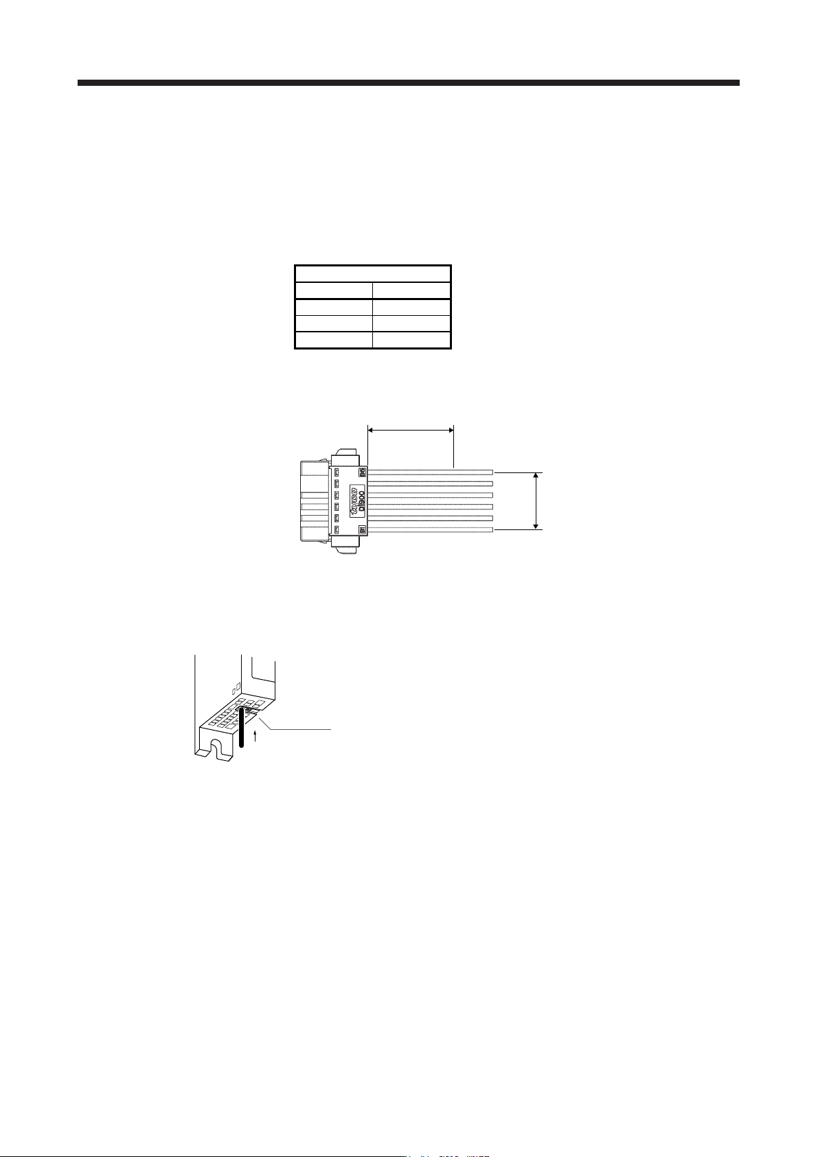
(5) Others
(a) Fix a cable tie at least distance of "A" × 1.5 away from the end of the connector.
A × 1.5 or more
A
(b) Be sure that wires are not pulled excessively when the connector is inserted.
App. 5.8.4 Wiring FG
Bottom face
Lead wire
Wire range
Single wire: φ 0.4 mm to 1.2 mm (AWG 26 to AWG 16)
Stranded wire: 0.2 mm
2
to 1.25 mm
2
(AWG 24 to AWG 16),
wire φ 0.18 mm or more
APPENDIX
App. - 18
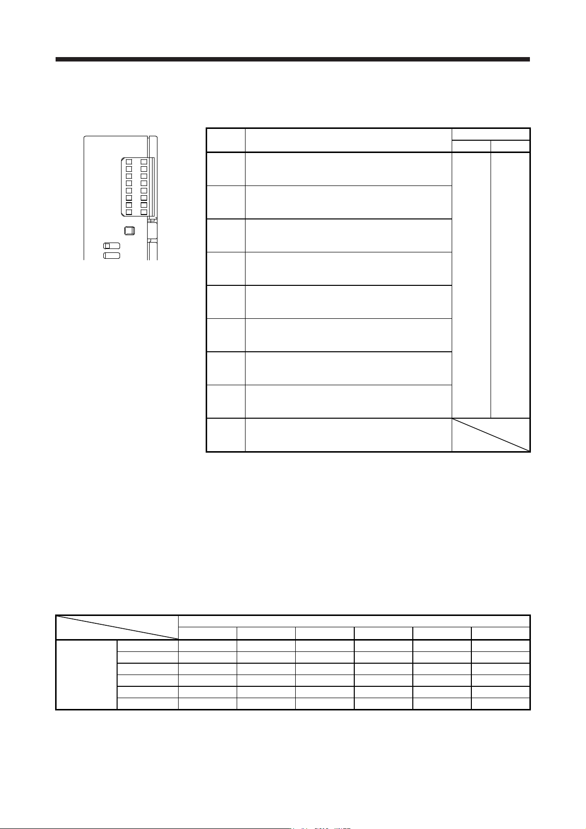
App. 5.9 LED display
I/O status, malfunction and power on/off are displayed with LED for each A-axis and B-axis.
MR-J3-D05
SRES
AB
SDI1
SDI2
TOF
SDO1
SDO2
SW
FAULT
POWER
LED Definition
LED
Column A Column B
SRES
Monitor LED for start/reset
Off: The start/reset is off. (The switch contact is opened.)
On: The start/reset is on. (The switch contact is closed.)
A-axis B-axis
SDI1
Monitor LED for shut-off 1
Off: The shut-off 1 is off. (The switch contact is closed.)
On: The shut-off 1 is on. (The switch contact is opened.)
SDI2
Monitor LED for shut-off 2
Off: The shut-off 2 is off. (The switch contact is closed.)
On: The shut-off 2 is on. (The switch contact is opened.)
TOF
Monitor LED for STO state
Off: Not in STO state
On: In STO state
SDO1
Monitor LED for SDO1
Off: Not in STO state
On: In STO state
SDO2
Monitor LED for SDO2
Off: Not in STO state
On: In STO state
SW
Monitor LED for confirming shutdown delay setting
Off: The settings of SW1 and SW2 do not match.
On: The settings of SW1 and SW2 match.
FAULT
FAULT LED
Off: Normal operation (STO monitoring state)
On: Fault has occurred.
POWER
Power
Off: Power is not supplied to MR-J3-D05.
On: Power is being supplied to MR-J3-D05.
App. 5.10 Rotary switch setting
Rotary switch is used to shut off the power after control stop by SS1 function.
Set the delay time from when the STO shut off switch is pressed until when STO output is performed. Set the
same setting for SW1 and SW2. The following table shows the delay time to be set according to the setting
value of the rotary switch.
Setting cannot be changed while power is on. Notify users that setting cannot be changed by putting a seal
or by another method so that end users will not change the setting after the shipment.
0 to F in the following table is the set value of the rotary switches (SW1 and SW2).
Rotary switch setting and delay time at A-axis/B-axis [s]
B-axis
0 s 1.4 s 2.8 s 5.6 s 9.8 s 30.8 s
0 s 0 1 2 - 3 4
1.4 s - - 5 - 6 7
A-axis
2.8 s - - 8 - 9 A
5.6 s - - - - B C
9.8 s - - - - D E
30.8 s - - - - - F