sh030106u.pdf - 第159页
5. PARAMETE RS 5 - 14 No. Sym bol Name and function Initial value [unit] Setting range PA08 A TU Aut o tuning mode Select the gain adjustment mode. Refer to t he "Name and function" c olumn. Setting digit Expla…
5. PARAMETERS
5 - 13
No. Symbol Name and function
Initial
value
[unit]
Setting
range
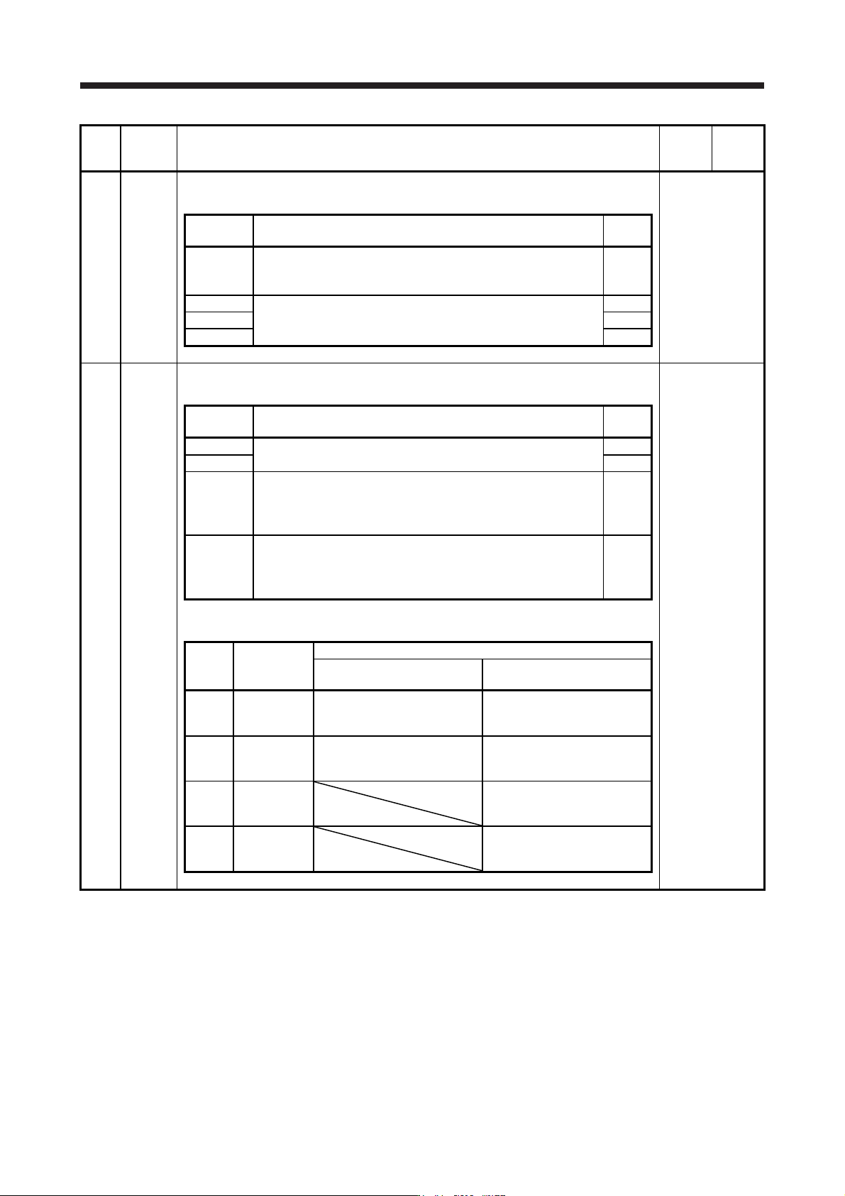
PA03 *ABS Absolute position detection system
Set this parameter when using the absolute position detection system.
Refer to the
"Name and
function" column.
Setting
digit
Explanation
Initial
value
_ _ _ x Absolute position detection system selection
0: Disabled (used in incremental system)
1: Enabled (used in absolute position detection system)
0h
_ _ x _ For manufacturer setting 0h
_ x _ _ 0h
x _ _ _ 0h
PA04 *AOP1 Function selection A-1
This is used to select the forced stop input and forced stop deceleration function.
Refer to the
"Name and
function" column.
Setting
digit
Explanation
Initial
value
_ _ _ x For manufacturer setting 0h
_ _ x _ 0h
_ x _ _ Servo forced stop selection
0: Enabled (The forced stop input EM2 or EM1 is used.)
1: Disabled (The forced stop input EM2 and EM1 are not used.)
Refer to table 5.1 for details.
0h
x _ _ _ Forced stop deceleration function selection
0: Forced stop deceleration function disabled (EM1)
2: Forced stop deceleration function enabled (EM2)
Refer to table 5.1 for details.
2h
Table 5.1 Deceleration method
Setting
value
EM2/EM1
Deceleration method
EM2 or EM1 is off
Controller forced stop is
enabled/Alarm occurred
0 0 _ _ EM1
MBR (Electromagnetic brake
interlock) turns off without the
forced stop deceleration.
MBR (Electromagnetic brake
interlock) turns off without the
forced stop deceleration.
2 0 _ _ EM2
MBR (Electromagnetic brake
interlock) turns off after the
forced stop deceleration.
MBR (Electromagnetic brake
interlock) turns off after the
forced stop deceleration.
0 1 _ _
Not using
EM2 and
EM1
MBR (Electromagnetic brake
interlock) turns off without the
forced stop deceleration.
2 1 _ _
Not using
EM2 and
EM1
MBR (Electromagnetic brake
interlock) turns off after the
forced stop deceleration.
5. PARAMETERS
5 - 14
No. Symbol Name and function
Initial
value
[unit]
Setting
range
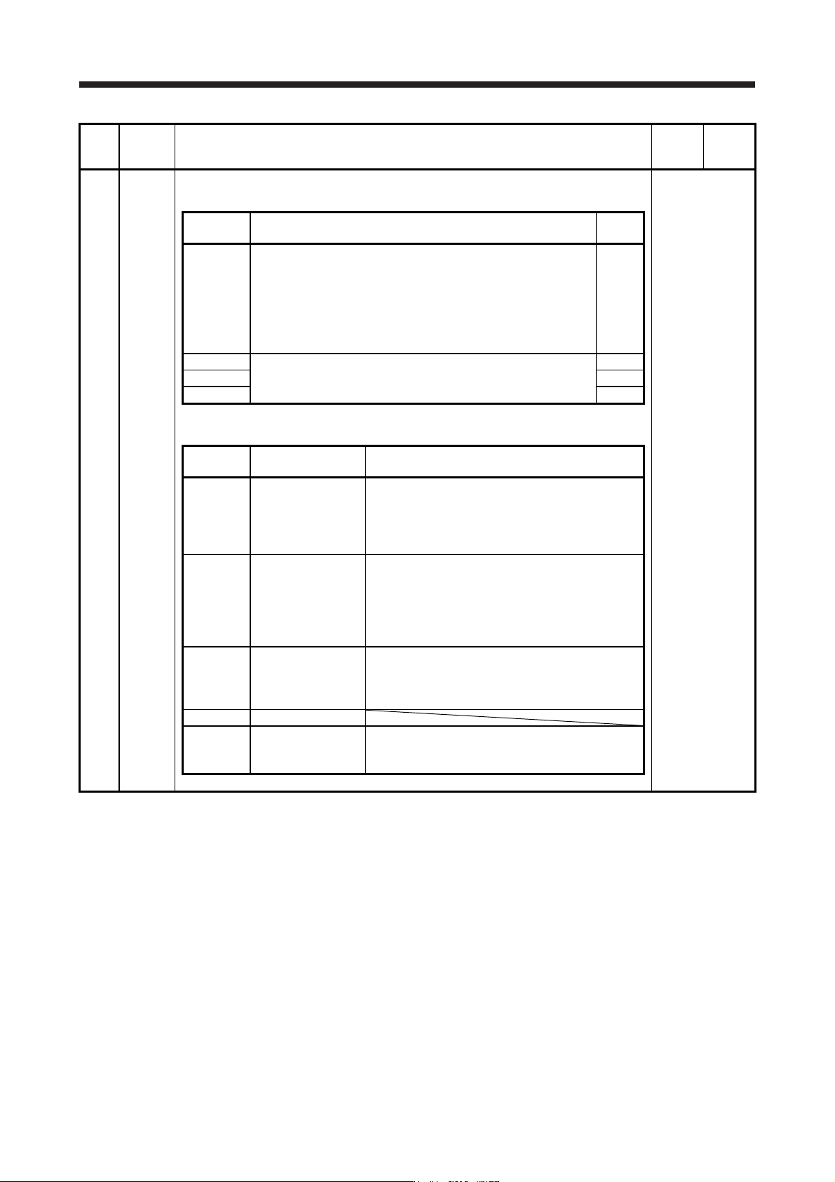
PA08 ATU Auto tuning mode
Select the gain adjustment mode.
Refer to the
"Name and
function" column.
Setting
digit
Explanation
Initial
value
_ _ _ x Gain adjustment mode selection
0: 2 gain adjustment mode 1 (interpolation mode)
1: Auto tuning mode 1
2: Auto tuning mode 2
3: Manual mode
4: 2 gain adjustment mode 2
Refer to table 5.2 for details.
1h
_ _ x _ For manufacturer setting 0h
_ x _ _ 0h
x _ _ _ 0h
Table 5.2 Gain adjustment mode selection
Setting
value
Gain adjustment
mode
Automatically adjusted parameter
_ _ _ 0
2 gain adjustment
mode 1
(interpolation mode)
[Pr. PB06 Load to motor inertia ratio/load to motor
mass ratio]
[Pr. PB08 Position loop gain]
[Pr. PB09 Speed loop gain]
[Pr. PB10 Speed integral compensation]
_ _ _ 1 Auto tuning mode 1
[Pr. PB06 Load to motor inertia ratio/load to motor
mass ratio]
[Pr. PB07 Model loop gain]
[Pr. PB08 Position loop gain]
[Pr. PB09 Speed loop gain]
[Pr. PB10 Speed integral compensation]
_ _ _ 2 Auto tuning mode 2 [Pr. PB07 Model loop gain]
[Pr. PB08 Position loop gain]
[Pr. PB09 Speed loop gain]
[Pr. PB10 Speed integral compensation]
_ _ _ 3 Manual mode
_ _ _ 4
2 gain adjustment
mode 2
[Pr. PB08 Position loop gain]
[Pr. PB09 Speed loop gain]
[Pr. PB10 Speed integral compensation]
5. PARAMETERS
5 - 15
No. Symbol Name and function
Initial
value
[unit]
Setting
range
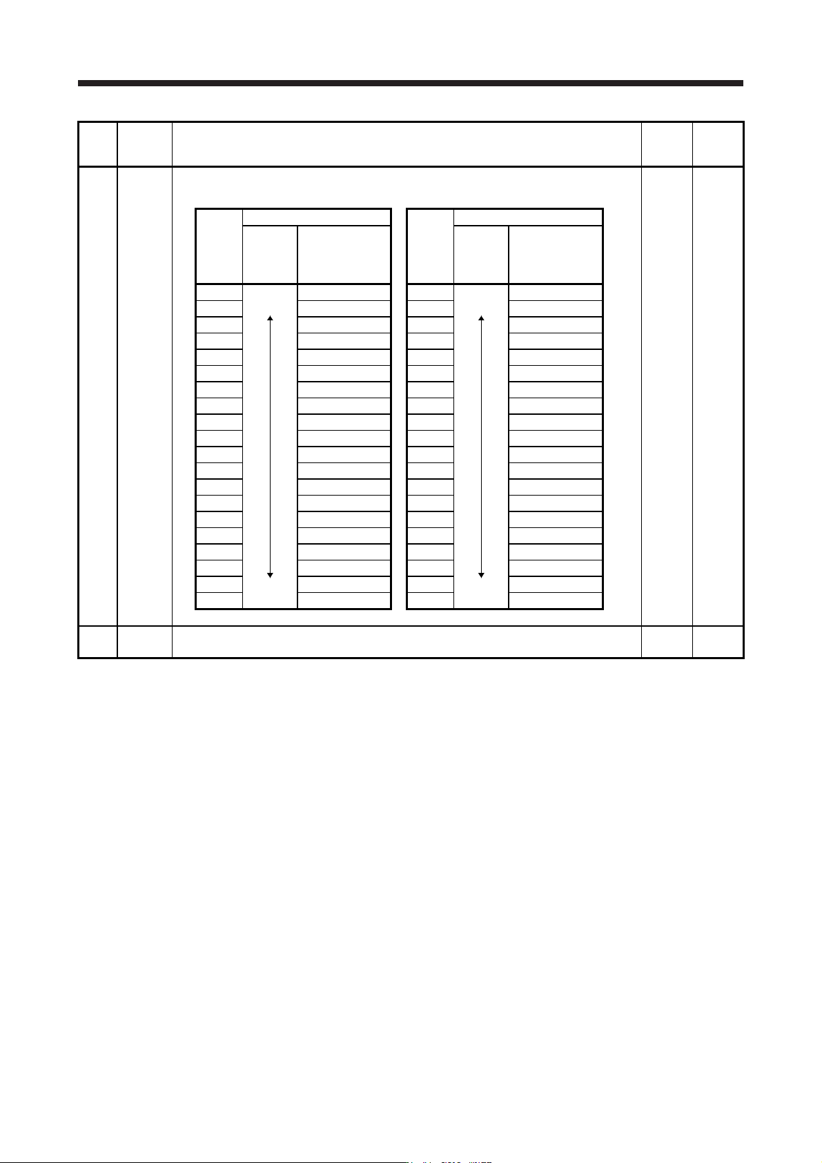
PA09 RSP Auto tuning response
Set a response of the auto tuning.
16 1 to 40
Setting
value
Machine characteristic
Setting
value
Machine characteristic
Response
Guideline for
machine
resonance
frequency [Hz]
Response
Guideline for
machine
resonance
frequency [Hz]
1
Low
response
Middle
response
2.7 21
Middle
response
High
response
67.1
2 3.6 22 75.6
3 4.9 23 85.2
4 6.6 24 95.9
5 10.0 25 108.0
6 11.3 26 121.7
7 12.7 27 137.1
8 14.3 28 154.4
9 16.1 29 173.9
10 18.1 30 195.9
11 20.4 31 220.6
12 23.0 32 248.5
13 25.9 33 279.9
14 29.2 34 315.3
15 32.9 35 355.1
16 37.0 36 400.0
17 41.7 37 446.6
18 47.0 38 501.2
19 52.9 39 571.5
20 59.6 40 642.7
PA10 INP In-position range
Set an in-position range per command pulse.
1600
[pulse]
0 to
65535