sh030106u.pdf - 第338页
11. OPT ION S AND P ERI PHER AL EQU IPMENT 11 - 17 (1) MR-J4-500 B(-RJ ) or les s/MR- J4-350B 4(-RJ) or less Always remove the w iring fr om across P+ to D a nd fit t he regene ra tive opt ion ac ross P+ to C. G3 and G4 …
11. OPTIONS AND PERIPHERAL EQUIPMENT
11 - 16
11.2.3 Parameter setting
Set [Pr. PA02] according to the option to be used.
Regenerative option selection
00: Regenerative option is not used.
For servo amplifier of 100 W, regenerative resistor is not used.
Built-in regenerative resistors are used on servo amplifiers with a
capacity of 0.2 kW to 7 kW.
Supplied regenerative resistors or regenerative option is used
with the servo amplifier of 11 kW to 22 kW.
01: FR-BU2/FR-BU2-H/FR-RC/FR-RC-H/FR-CV/FR-CV-H/FR-XC/FR-XC-H
02: MR-RB032
03: MR-RB12
04: MR-RB32
05: MR-RB30
06: MR-RB50 (Cooling fan is required)
08: MR-RB31
09: MR-RB51 (Cooling fan is required)
0B: MR-RB3N
0C: MR-RB5N (Cooling fan is required)
80: MR-RB1H-4
81: MR-RB3M-4 (Cooling fan is required.)
82: MR-RB3G-4 (Cooling fan is required.)
83: MR-RB5G-4 (Cooling fan is required.)
84: MR-RB34-4 (Cooling fan is required.)
85: MR-RB54-4 (Cooling fan is required.)
91: MR-RB3U-4 (Cooling fan is required.)
92: MR-RB5U-4 (Cooling fan is required.)
FA: When the supplied regenerative resistors or the regenerative
option is cooled by the cooling fan to increase the ability with
the servo amplifier of 11 kW to 22 kW.
00
[Pr. PA02]
11.2.4 Connection of regenerative option
POINT
When MR-RB50, MR-RB51, MR-RB5N, MR-RB3M-4, MR-RB3G-4, MR-RB5G-
4, MR-RB34-4, MR-RB54-4, MR-RB5K-4, or MR-RB6K-4 is used, a cooling fan
is required to cool it. The cooling fan should be prepared by the customer.
For the wire sizes used for wiring, refer to section 11.9.
The regenerative option generates heat of 100 ˚C higher than the ambient temperature. Fully consider heat
dissipation, installation position, wires used, etc. before installing the option. For wiring, use flame-resistant
wires or make the wires flame-resistant and keep them away from the regenerative option. Use twisted wires
with a maximum length of 5 m for a connection with the servo amplifier.
11. OPTIONS AND PERIPHERAL EQUIPMENT
11 - 17
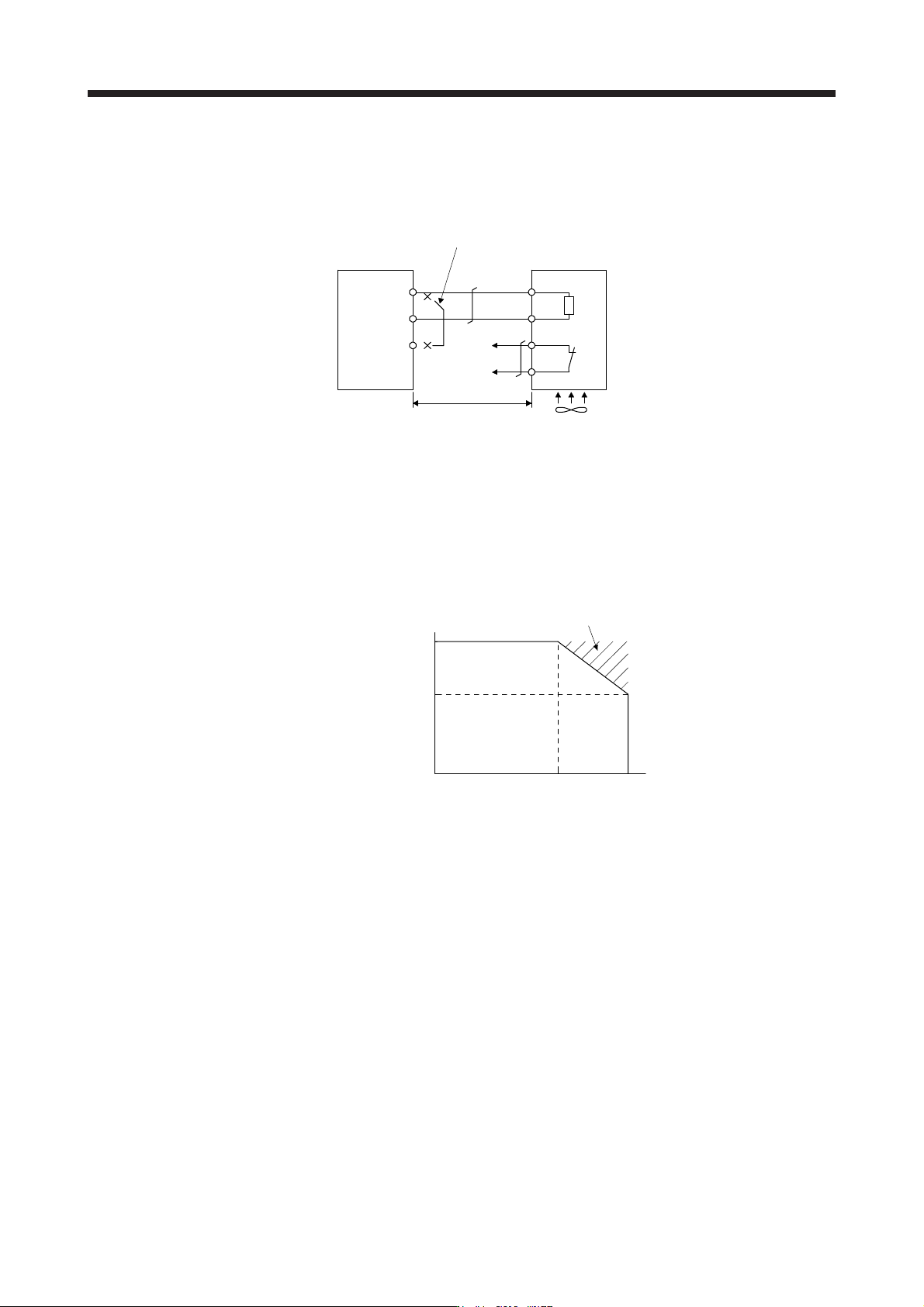
(1) MR-J4-500B(-RJ) or less/MR-J4-350B4(-RJ) or less
Always remove the wiring from across P+ to D and fit the regenerative option across P+ to C. G3 and G4
are thermal sensor's terminals. Between G3 and G4 is opened when the regenerative option overheats
abnormally.
D
P+
C
G4
G3
C
P
Regenerative option
5 m or less
Servo amplifier
Always remove the lead from across P+ to D
.
(Note 3)
Cooling fan
(Note 1, 2)
Note 1. When using the MR-RB50, MR-RB5N, MR-RB51, MR-RB3M-4, MR-RB3G-4, or
MR-RB5G-4, forcibly cool it with a cooling fan (1.0 m
3
/min or more, 92 mm × 92
mm
)
.
2. When the ambient temperature is more than 55 °C and the regenerative load
ratio is more than 60% in MR-RB30, MR-RB31, MR-RB32, and MR-RB3N,
forcefully cool the air with a cooling fan (1.0 m
3
/min or more, 92 mm × 92 mm). A
cooling fan is not required if the ambient temperature is 35 °C or less. (A cooling
fan is required for the shaded area in the followin
g
g
raph.
)
100
60
0
0
Ambient temperature [°C]
35 55
A cooling fan is
not required.
A cooling fan is required.
Load ratio [%]
3. Make up a sequence which will switch off the magnetic contactor when abnormal
heating occurs.
G3-G4 contact specifications
Maximum voltage: 120 V AC/DC
Maximum current: 0.5 A/4.8 V DC
Maximum capacit
y
: 2.4 V
A
11. OPTIONS AND PERIPHERAL EQUIPMENT
11 - 18
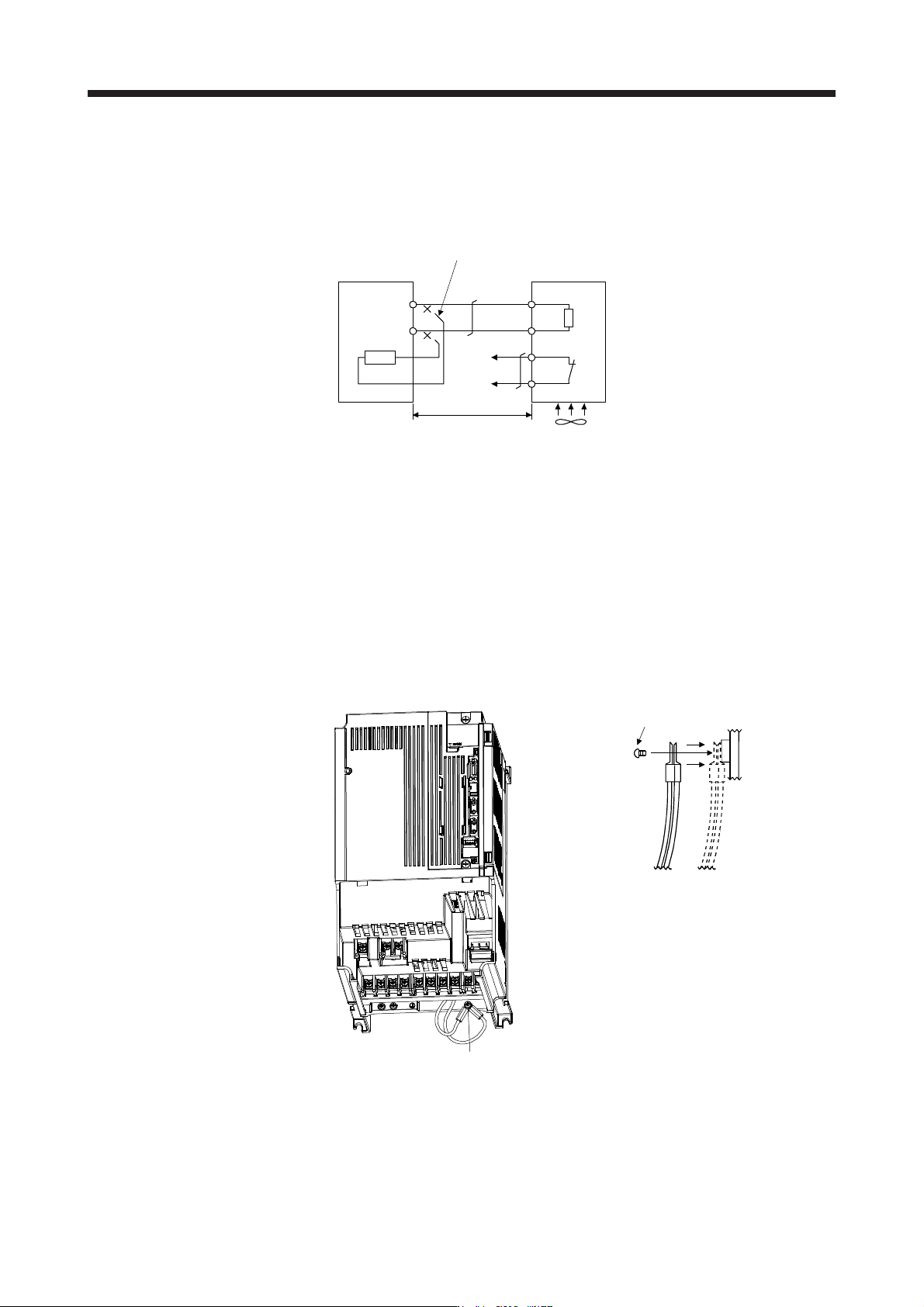
(2) MR-J4-500B4(-RJ)/MR-J4-700B(-RJ)/MR-J4-700B4(-RJ)
Always remove the wiring (across P+ to C) of the servo amplifier built-in regenerative resistor and fit the
regenerative option across P+ to C. G3 and G4 are thermal sensor's terminals. Between G3 and G4 is
opened when the regenerative option overheats abnormally.
Always remove the wiring (across P+ to C) of the servo
amplifier built-in regenerative resistor.
P+
C
G4
G3
C
P
Regenerative option
5 m or less
Servo amplifier
(Note 2)
Cooling fan
(Note 1)
Note 1. When using the MR-RB51, MR-RB34-4, MR-RB54-4, MR-RB3U-4, or MR-RB5U-
4, forcibl
y
cool it with a coolin
g
fan
(
1.0 m
3
/
min or more, 92 mm × 92 mm
)
.
2. Make up a sequence which will switch off the magnetic contactor when abnormal
heating occurs.
G3-G4 contact specifications
Maximum voltage: 120 V AC/DC
Maximum current: 0.5 A/4.8 V DC
Maximum capacit
y
: 2.4 V
A
When using the regenerative option, remove the servo amplifier's built-in regenerative resistor wires
(across P+ to C), fit them back to back, and secure them to the frame with the accessory screw as
shown below.
Built-in regenerative resistor
lead terminal fixing screw
Accessory screw