sh030106u.pdf - 第328页
11. OPT ION S AND P ERI PHER AL EQU IPMENT 11 - 7 11.1.3 SSCN ET II I cable POINT Do not look direc tly at the light g enerated from C N1A/CN1B c onn ec tor of s ervo amplifier or the end of SSCNET III cabl e. The ligh t…
11. OPTIONS AND PERIPHERAL EQUIPMENT
11 - 6
11.1.2 MR-D05UDL3M-B STO cable
This cable is for connecting an external device to the CN8 connector.
Cable model Cable length Cable OD (Note) Application
MR-D05UDL3M-B 3 m 5.7 mm Connection cable for the CN8 connector
Note. Standard OD. The maximum OD is about 10 %
g
reater for dimensions without tolerances.
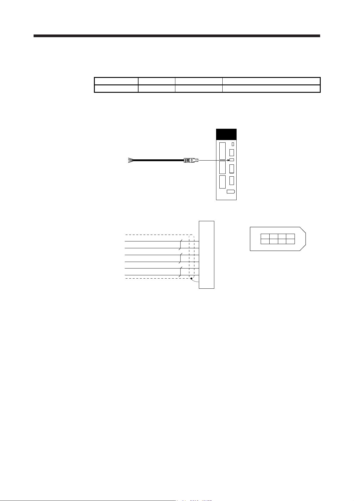
(1) Configuration diagram
Servo amplifier
MR-D05UDL3M-B
CN8
(2) Internal wiring diagram
1
2
3
6
7
Plate
STO2
TOFB1
TOFB2
Shield
STO1
TOFCOM
8
4
5
STOCOM
Yellow (with black dots)
Yellow (with red dots)
Gray (with black dots)
Gray (with red dots)
White (with black dots)
White (with red dots)
(Note)
2
1
64 8
CN8 connector
357
Viewed from the connection part
Note. Do not use the two core wires with oran
g
e insulator
(
with red or black dots
)
.
11. OPTIONS AND PERIPHERAL EQUIPMENT
11 - 7
11.1.3 SSCNET III cable
POINT
Do not look directly at the light generated from CN1A/CN1B connector of servo
amplifier or the end of SSCNET III cable. The light can be a discomfort when it
enters the eye.
Refer to app. 10 for long distance cable over 50 m and ultra-long bending life
cable.
(1) Model explanations
The numbers in the cable length field of the table indicate the symbol filling the underline "_" in the cable
model. The cables of the lengths with the symbols are available.
Cable model
Cable length
Bending
life
Application/remark
0.15 m 0.3 m 0.5 m 1 m 3 m 5 m 10 m 20 m 30 m 40 m 50 m
MR-J3BUS_M 015 03 05 1 3 Standard
Using standard cord
inside cabinet
MR-J3BUS_M-A 5 10 20 Standard
Using standard cable
outside cabinet
(Note)
MR-J3BUS_M-B
304050
Long
bending
life
Using long distance
cable
Note. For cable of 30 m or shorter, contact
y
our local sales office.
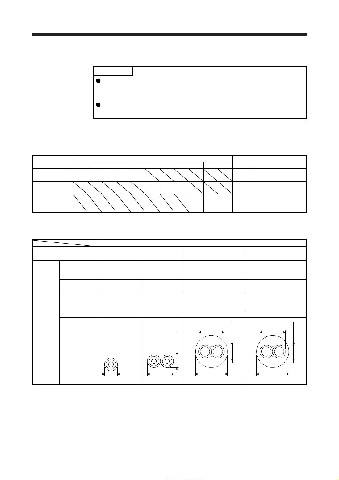
(2) Specifications
Description
SSCNET III cable model MR-J3BUS_M MR-J3BUS_M-A MR-J3BUS_M-B
SSCNET III cable length 0.15 m 0.3 m to 3 m 5 m to 20 m 30 m to 50 m
Optical
cable
(cord)
Minimum bend
radius
25 mm
Enforced covering cable:
50 mm
Cord: 25 mm
Enforced covering cable:
50 mm
Cord: 30 mm
Tension strength 70 N 140 N
420 N
(Enforced covering cable)
980 N
(Enforced covering cable)
Temperature
range for use
(Note)
-40 °C to 85 °C -20 °C to 70 °C
Ambience Indoors (no direct sunlight), no solvent or oil
Appearance [mm]
2.2 ± 0.07
4.4 ± 0.1
2.2 ± 0.07
4.4 ± 0.1
6.0 ± 0.2
2.2 ± 0.07
4.4 ± 0.4
7.6 ± 0.5
2.2 ± 0.2
Note. This temperature range for use is the value for optical cable (cord) only. Temperature condition for the connector is the same as
that for servo amplifier.
11. OPTIONS AND PERIPHERAL EQUIPMENT
11 - 8
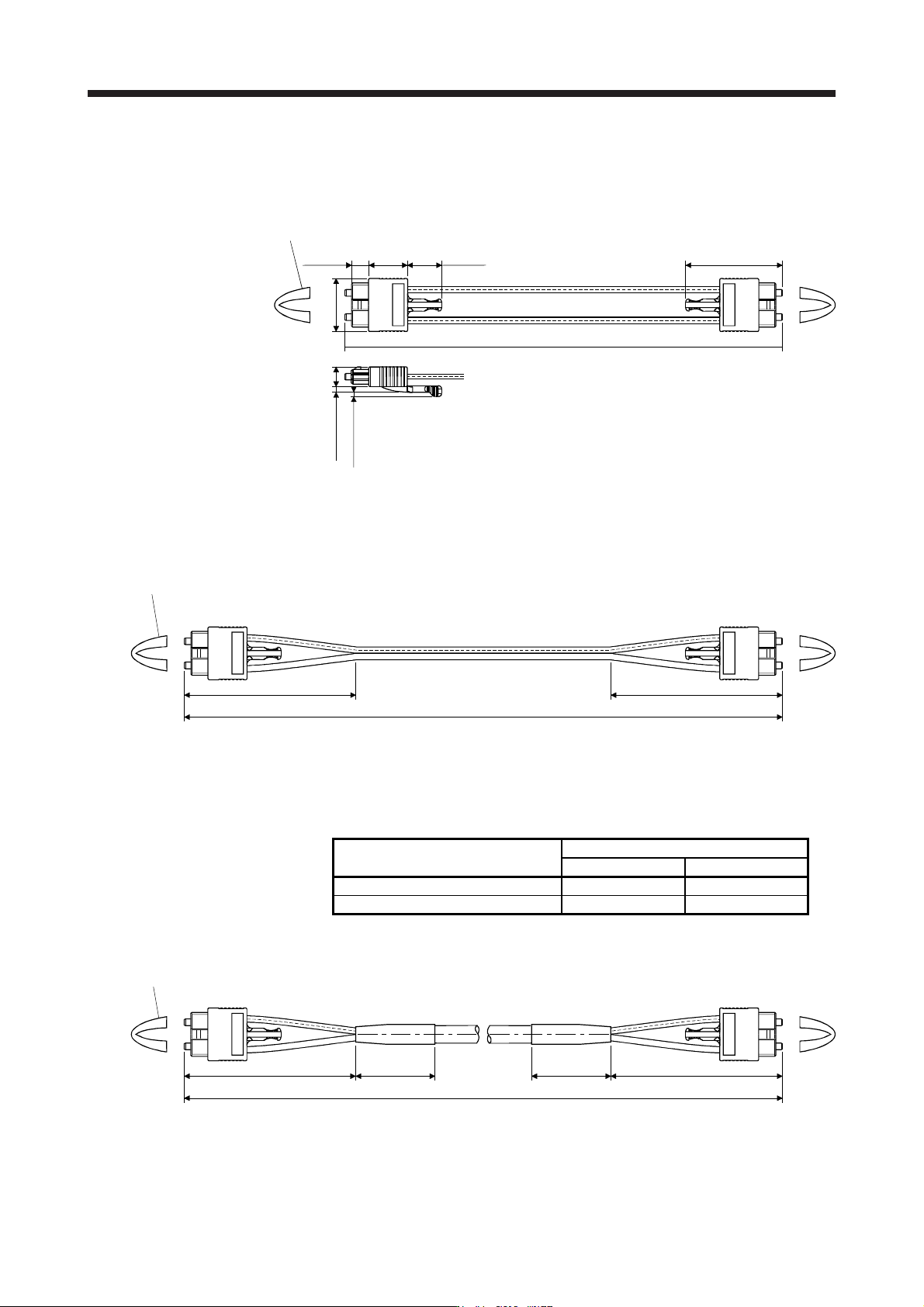
(3) Dimensions
(a) MR-J3BUS015M
[Unit: mm]
150
Approx.
6.7
8
+0
+50
- 0
Protective tube
Approx.
15
Approx.
13.4
Approx.
20.9
Approx. 2.3
Approx. 1.7
Approx.
37.65
(b) MR-J3BUS03M to MR-J3BUS3M
Refer to the table shown in (1) in this section for cable length (L).
[Unit: mm]
L
(Note)
Protective tube
Approx. 100
Approx. 100
Note. Dimension of connector part is the same as that of MR-J3BUS015M.
(c) MR-J3BUS5M-A to MR-J3BUS20M-A/MR-J3BUS30M-B to MR-J3BUS50M-B
Refer to the table shown in (1) in this section for cable length (L).
SSCNET III cable
Variable dimensions [mm]
A B
MR-J3BUS5M-A to MR-J3BUS20M-A 100 30
MR-J3BUS30M-B to MR-J3BUS50M-B 150 50
[Unit: mm]
L
Protective tube
(Note)
Approx. A Approx. B Approx. B Approx. A
Note. Dimension of connector part is the same as that of MR-J3BUS015M.